
Search for your product name or keyword
XL4015 1.2V – 32V 5A DC-DC Step-down Buck CC/CV Battery Charger LED Driver with Volt, Amp & Power Meter
 This XL4015-based voltage converter is a 180 KHz fixed frequency PWM buck (step-down) DC/DC module with Constant Voltage and Constant Current control, capable of driving a 5A load with high efficiency, low ripple, and excellent line and load regulation.
It is a very flexible and adaptable charging solution that can provide either a Constant Voltage (CV) or Constant Current (CC) output. With a variable output voltage range of 1.2V to 34V and variable output current from 0A to 5A peak (4A continuous), it is ideal for use as an LED or laser diode current source/driver, a battery charger, a lab current/voltage source, or to regulate the output of solar panels or wind turbines to charge energy storage batteries. It can charge most any size lithium-ion cell to almost any voltage you need. This is an inexpensive way to charge 4.30V and 4.35V cells, as well as LiFePo and many other cells that require different termination voltages. It is also a good way to charge smaller cells since you can almost infinitely adjust the charging current and output voltage
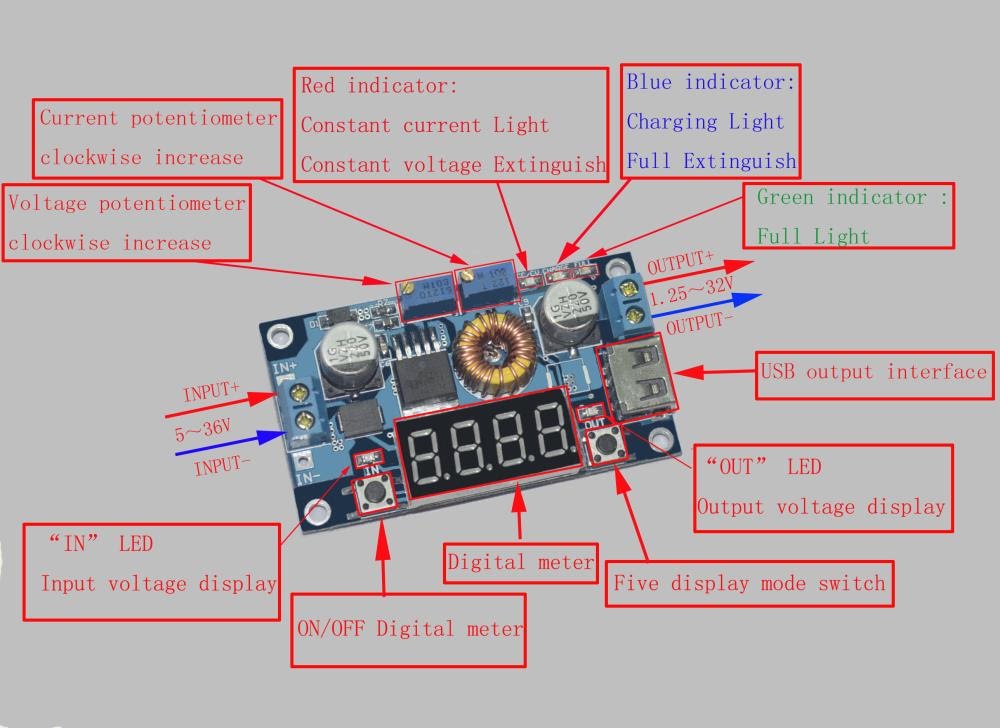
The module features a meter that displays the input voltage and output voltage (V), output current (A), and output power (W), eliminating the need for external voltage, current, and power meters for setup and monitoring.
Features:
- Digital meter displays input and output voltages, output current, and output power.
- Operates in Constant Current (CC) or Constant Voltage (CV) mode, optimum for driving LEDs, laser diodes, charging batteries, and as a general-purpose voltage and current source.
- The left button enables and disables the meter display. Right button switches between the input or output voltages, current, or power, or selects a continuous scrolling display of the parameters. “In” and “Out” LEDs indicate whether the meter is displaying the input or the output voltage.
- The voltmeter can be calibrated to ensure measurement accuracy.
- Screw terminal input connections, screw terminals, or USB connector for the output.
Specifications:
- Input voltage range: 5V – 36VDC
- Output voltage range: 1.2V – 34VDC adjustable via onboard potentiometer
(Input voltage must be at least 2V greater than output voltage) - Output current: 0A – 5A peak, 4A continuous (see Notes below)
- Output power: 75W maximum
- Voltmeter range: 1.2V to 40.0V, 0.1V display resolution
- Current meter range: 0.00A to 5.00A, 0.01A display resolution
- Power meter range: 0.0W to 99.9W, 0.1W display resolution
- Electrical Isolation: Non-Isolated
Operation:
- Turn off the input voltage, and connect to the IN+ and IN- screw terminals. Turn on the input power. The Power On LED will illuminate.
- The Meter is turned on and off with the left ON/OFF button. The parameter to display is selected with the right Mode Select button: Input Voltage, Output Voltage, Output Current, Output Power, and scrolling (the display will continuously scroll through the parameters). The IN and OUT LEDs indicate whether the meter is displaying the input or the output voltage.
To use as an LED or Laser Diode Constant Current Driver or General-Purpose Voltage/Current Source:
- Make sure of the operating current and maximum operating voltage of the LED or Laser Diode you will drive.
- With no load connected, adjust the right button so that the “OUT” LED is illuminated. The digital meter shows the value of the output voltage. Adjust the “voltage potentiometer” so that the output voltage reaches the value you want.
- Adjust the right button so that the digital meter shows the value of the output current. Using a wire or jumper, short the output terminals, then adjust the “current potentiometer” so that the output current reaches the overcurrent protection value.
- Connect the module to the LED or Laser using the output terminals.
- If the current drawn by the LED or laser is less than the maximum current setpoint, the driver will be operating in Constant Voltage (CV) mode, the red Constant Current LED will be off, and the green “Full” LED will be on. The actual current delivered to the load can be determined by selecting Output Current on the meter.
- If the current drawn by the LED is greater than the maximum current setpoint, the driver will be operating in Constant Current (CC) mode, the red Constant Current LED will be on, and the green “Full” LED will be off. The actual voltage delivered to the load can be determined by selecting Output Voltage on the meter.
- The module can drive multiple LEDs in series, parallel or in series/parallel strings, as long as the maximum voltage and current of the string does not exceed the 32V maximum output voltage and 4.5A maximum output current of the driver module.
To use as a Battery Charger:
- Make sure you know the battery float voltage and charging current. If it is a lithium cell with parameters of 3.7V/2200mAh, then the float voltage is 4.2V, the maximum charging current 1C, ie 2200mA).
- With no load connected, adjust the“Voltage potentiometer” to set the output voltage to the float voltage; (i.e. if a 3.7V rechargeable lithium battery, the output voltage can be adjusted to 4.2V).
- Adjust the right button so that the digital meter shows the value of output current. Using a jumper or wire short the output terminal, then adjust the “Current Potentiometer” so that the output current reaches the predetermined Charging current value.
- The blue Charging LED current factory default is 0.1 times the charging current. During charging the current to the battery gradually decreases, when the current reaches 0.1 the current setpoint, the Charging LED will turn off, and the Green Fully Charged Lamp will turn on, indicating that the battery is fully charged.
Voltmeter Calibration
Output voltage calibration:
- Adjust the right button so that the “OUT” LED is illuminated, the voltmeter shows the value of output voltage. Press the right button for more than 2 seconds, release, voltmeter and “OUT” LED flashes in synchronization so that you enter the output voltage calibration mode.
- Press the right button (normal speed), the voltage value will increase a unit; press the left button, decrease a unit. Due to a unit being less than 0.1V and the minimum voltage display being 0.1V, you need to continuously press 1-5 times to see the voltmeter change 0.1V. The number of times the button must be pressed to change 0.1V depends on the current display voltage, the higher the voltage, the fewer the number of presses.
- Press the right button for more than 2 seconds and release to exit the output voltage calibration mode. All parameters are automatically saved.
Input voltage calibration:
- Adjust the right button so that “IN” LED is illuminated, the voltmeter shows the value of input voltage. Press the right button for more than 2 seconds, release, voltmeter and “IN” LED flashes in synchronization so that you enter the input voltage calibration mode.
- Steps 2 and 3, are the same as the output voltage calibration.
Notes:
- The voltage on the USB connector is the module’s output voltage, not a fixed 5V output. When using the module to power USB-powered digital equipment, make sure the output voltage is set to 5V before connecting anything to the USB connector.
- Always set the output voltage and current before connecting a load.
- For maximum efficiency, the output voltage level should be about 80% of the input voltage level.
- Operation above 2A continuous current may require heatsinking and/or forced air cooling of the XL4015 IC and the LM317 regulator on the back of the circuit board.
Other References:
Mastering the XL4015 Step-Down Converter with display: A simple Guide video by Electronix on Youtube
Copyright © 2018-2024 Envistia Mall
www.envistiamall.com
P/N EM-POWER-0028