
Search for your product name or keyword
W1209 12V -50° to 110°C Digital Thermostat Temperature Controller Module Installation and Operating Instructions
This user manual provides instructions for installing and operating the W1209 digital thermostat temperature controller module. This module is designed for hobbyists and electronic DIYers with a basic understanding of electronics.
Estas instrucciones están disponibles en español: W1209 Instrucciones de instalación y funcionamiento del módulo controlador de temperatura del termostato digital
INTRODUCTION
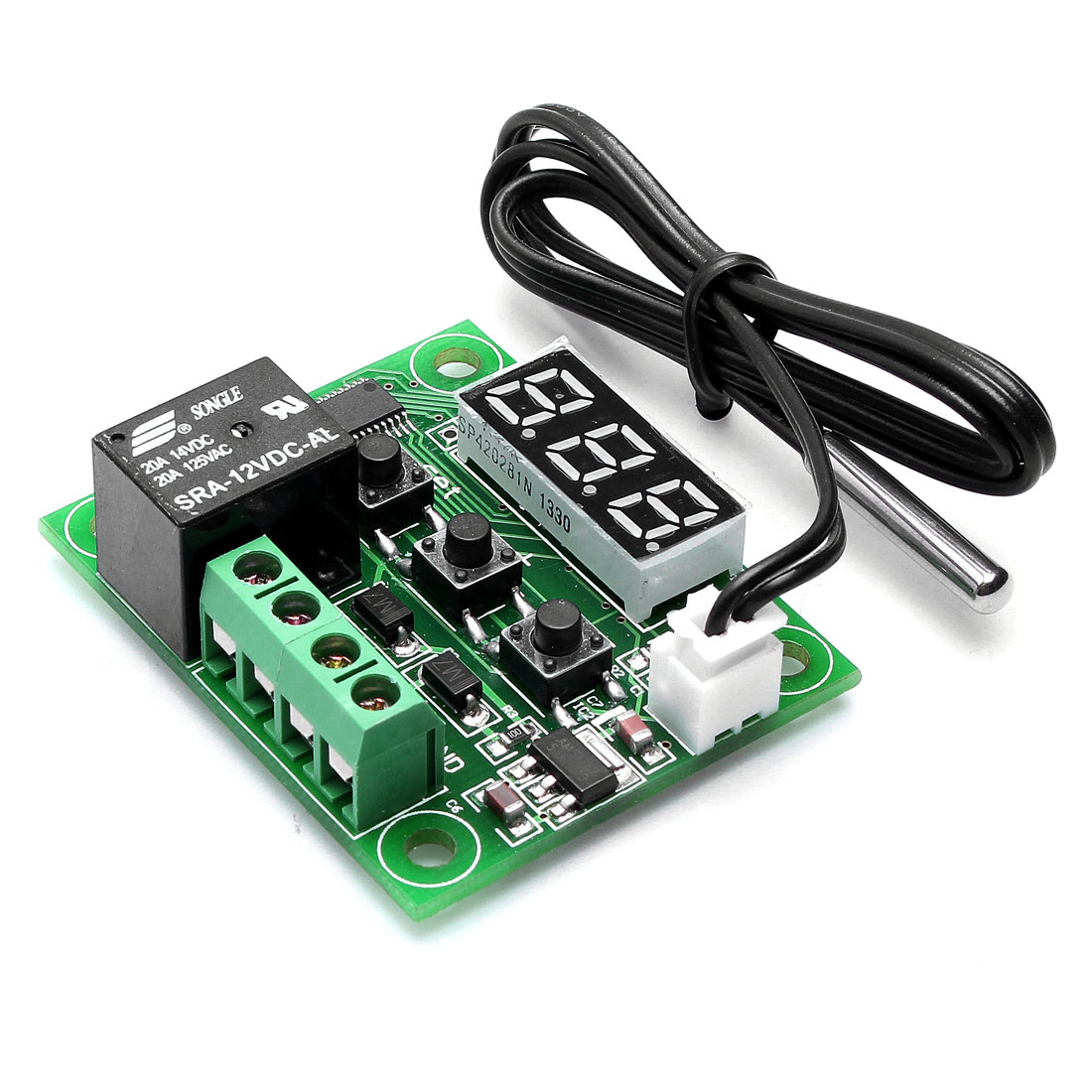
The W1209 is a compact and versatile temperature controller module that allows you to automate the operation of heating or cooling devices based on real-time temperature readings. It features a built-in relay that can switch power to connected devices such as fans, heaters, heat lamps or coolers, a 3-digit digital display, and three buttons (Set, Increase, Decrease) for easy configuration.
READ THIS FIRST!
- The W1209 is a temperature-controlled switch, not a power supply. When the actual temperature crosses the trigger level (see “Setting the Trigger Setpoint Temperature” below), the W1209 turns the relay on or off. Power is not automatically connected to the load. Your power supply must be connected to the load through the K0 and K1 relay connections. See “W1209 ELECTRICAL CONNECTION” below for details on how to wire the W1209 in your application.
- The “Trigger” temperatures at which the W1209 turns ON (closes the relay) and turns OFF (opens the relay) are determined by the temperature Setpoint and the Hysteresis (P1) values. See the sections below for setting the Trigger temperatures in Cooling and Heating modes.
In most applications, The only settings that need to be changed are the Mode (P0) to set it to Heating or Cooling mode, Hysteresis (P1) and the temperature Setpoint. Parameters P2 through P8 usually do not need to be changed. Ensure that you understand the effect of changing these parameters from their defaults before doing so. - The module only displays the temperature in Degrees Celsius (C). It cannot be changed to Fahrenheit (F).
- Envistia offers W1209 models with 5V and 24V support power in addition to the standard 12V model. These instructions also apply to the 5V and 24V models, except that the support voltages should be limited to 5V or 24V, respectively.
W1209 ELECTRICAL CONNECTION
PLEASE NOTE: The power supply is not automatically connected to the load. Your power supply must be connected to the load through the K0 and K1 relay connections, as detailed below.
The W1209 can use either a single 12V power source, or it can use two power sources, a 12V power supply to provide support power to the W1209’s circuitry, and a second DC or AC power supply to provide power to your load.
If you are using a single 12V power supply, it must be connected to both the +12V and the K1 relay connection on the W1209. See the section “Connecting the W1209 With a Single 12V DC Power Supply” below for more details.
If you are using a separate AC or DC power supply to power your device, rather than using a single 12V DC supply, it should be connected to the K0 relay connection, and the power lead for the load device is connected to K1, and 12V power for the W1209 is connected to the +12V terminal. See the section “Connecting the W1209 With a 12V DC Power Supply and a Separate Power Supply for the Load” below for more details.
Connecting the W1209 With a Single 12V DC Power Supply
Power the W1209:
- Connect the positive (+) terminal of the 12V power supply to the +12V terminal.
- Connect the negative (–) terminal to the GND terminal.
Connect your device to the relay:
- The relay terminals are labeled K0 (normally open), K1 (common).
- Connect the positive (+) terminal of the 12V power supply to the K1 terminal. In this configuration, the +12V and K1 terminals are both connected to the +V of the 12V power supply.
- Connect K0 to the +V input (typically the red wire) of your load.
- Connect the +12V power supply ground (-V) and the ground connection from your load to the GND terminal of the W1209 to complete the circuit when the relay is closed.
Interconnection drawing when using a single 12VDC power supply to power both the W1209 and the load

Connecting the W1209 with a 12V DC Power Supply and a Separate Power Supply for the Load
Power the W1209:
- Connect the positive (+) terminal of the 12V power supply to the +12V terminal.
- Connect the negative (–) terminal to the GND terminal.
Connect your device to the relay:
- The relay terminals are labeled K0 (normally open), K1 (common).
- Connect the positive (+) terminal of the device’s power supply to the K0 terminal.
- Connect the K1 terminal to the +V input (typically the red wire) of your load.
- Connect the device’s power supply ground (-V) and the ground connection to your load together to complete the circuit when the relay is closed.
Interconnection drawing when using a 12VDC power supply to power the W1209 and a separate power supply to power the load
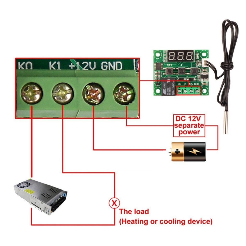
In this configuration, the 12V DC power supply only powers the W1209’s circuitry. The load power supply is only connected to your load, through the relay contact K0 and K1. So when the relay closes, the load device turns on. When the relay opens, the load device turns off.
Using the W1209 With a 12V Battery And Alternator or Generator
The W1209’s maximum input voltage should not exceed 12V. In applications where the battery voltage can exceed 12V (e.g., automobiles & RVs when the battery is being charged by its alternator), a voltage regulating circuit or device is recommended to prevent damage to the W1209.
Option 1: Buck Voltage Converter
A 12V to 9V buck voltage DC/DC converter with the input to the converter connected to the battery and the output to the W1209 will provide a stable, regulated 9V DC supply for the W1209.
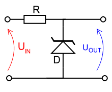
Option 2: Zener Diode and Resistor
A simple regulator circuit to limit the voltage to 12V can be built using a 1N5349A Zener diode and a 20 Ohm 1W series resistor. The schematic below shows how the resistor and diode should be connected:
In both of these configurations, the load device is usually connected straight to the battery and not through the buck converter or regulator circuit.
PROGRAMMING AND OPERATING THE W1209
Displaying the Current Temperature
If you apply power to the module without the sensor attached, it will display “LLL” or “888”. When you plug in the sensor, it will display the current temperature in degrees C. When in any other mode, when no input is detected for approximately 5 seconds. the W1209 will return to this default display.
Setting the Trigger Setpoint Temperature
To set the trigger Setpoint temperature, tap the button marked ‘SET’. The display will flash. You can now set a trigger temperature in 0.1°C increments using the ‘+’ and ‘-‘ buttons. If no buttons are pressed for approximately 2 seconds the trigger temperature will be stored and the display will return back to the current temperature.
How to Set the W1209’s Parameters
To set any parameter first press the ‘SET’ button for at least 5 seconds. The display should now display ‘P0’. This represents parameter P0. Pressing the ‘+’ or ‘-‘ buttons will cycle through the various parameters (P0 to P6). Pressing the ‘SET’ button while any of the parameters are displayed will allow you to change the value for that parameter using the ‘+’ and ‘-‘ buttons (see below). When finished setting a parameter press the ‘SET’ button to exit that option. If no buttons are pressed for approximately 5 seconds the thermostat will exit the parameter options and will return back to the default temperature display.
Setting the Cooling or Heating Parameter P0
The first parameter to set is the Mode (P0), which sets the W1209 in either Cooling Mode (C) or Heating Mode (H). The factory default is Cooling Mode (C). In Cooling mode, the relay will energize (turn on) when the trigger Setpoint temperature is reached. Use Cooling (C) if connecting the W1209 to a fan, air-conditioning system, chiller or other cooling device. When set to H, the relay will de-energize (turn off) when the temperature is reached. Use this setting if controlling a heating device such as a heat lamp or resistive heating coil.
All program settings are stored in non-volatile memory and are retained when power is removed from the module.
The photo below shows the W1209’s various components and settings.

Using the W1209 in Cooling Mode
In Cooling mode (P0 = “C”), the W1209 turns on (closes the relay, connecting K0 to K1) when the actual temperature reaches the trigger Setpoint temperature PLUS the Hysteresis value (P1), and turns off when the actual temperature drops down to the Setpoint temperature. For example, if the Setpoint temperature is set to 30C, and the Hysteresis (P1) is set to 2 degrees, the W1209 will turn on (meaning the relay will close) at 32 degrees, and will turn off when the temperature drops down to 30 degrees. If the Hysteresis is set to 4 degrees, then it will turn on at 34 degrees, and turn off at 30 degrees.
In other words, the trigger Setpoint temperature PLUS the Hysteresis temperature is the trigger temperature at which the W1209 will turn on (close the relay).
Example Settings for Cooling
- Set parameter P0 (Mode) to C for cooling (this is the factory default).
- Set parameter P1 (hysteresis) to 2 degrees.
- Set the Setpoint (Trigger) to 30C
- Wire a fan or other cooling device to the fan’s power supply with the fan’s +V connection connected to the power supply through the K0/K1 relay contacts. When the temperature measured by the sensor rises to 32C (the trigger Setpoint + Hysteresis P1), the relay will close, connecting the power supply to the fan, and the fan will turn on to cool. When the temperature drops down to 30C (the trigger Setpoint), the fan will turn off.
- The temperature difference between turn-on and turn-off is controller by the Hysteresis (P1). For example, if you wanted it to turn on at 35 degrees and off at 30 degrees, change the Hysteresis value P1 to 5 degrees.
Using the W1209 in Heating Mode
In Heating mode (P0 = “H”), the W1209 turns on when the actual temperature reaches the trigger Setpoint temperature MINUS the Hysteresis, and turns off when the actual temperature increases to the Setpoint temperature. For example, if the Setpoint temperature is set to 22C, and the Hysteresis (P1) is set to 2 degrees, the W1209 will turn on (meaning the relay will close) at 20 degrees, and will turn off when the temperature increases to 22 degrees. If the Hysteresis is set to 4 degrees, it will turn on at 18 degrees, and turn off at 22 degrees.
In other words, the trigger Setpoint temperature MINUS the Hysteresis temperature is the trigger temperature at which the W1209 will turn on (close the relay).
Example Settings for Heating
- Set parameter P0 (Mode) to H for heating.
- Set parameter P1 (hysteresis) to 2 degrees.
- Set the Setpoint (Trigger) to 15C
- Wire a heat lamp or other heating device to the lamp’s power supply with the lamp’s +V connection (usually a red wire) connected to the power supply through the K0/K1 relay contacts. When the temperature measured by the sensor drops to 13C (the trigger Setpoint – Hysteresis P1), the relay will close, connecting the power supply to the lamp, and the lamp will turn on to heat. When the temperature increases to 15C (the trigger Setpoint), the lamp will turn off.
- The temperature difference between turn-on and turn-off is controller by the Hysteresis (P1). For example, if you wanted it to turn on at 12 degrees and off at 15 degrees, change the Hysteresis value P1 to 3 degrees.
W1209 OPERATING PARAMETERS
In most applications, the only settings that need to be changed are the Mode (P0) to set it to Heating or Cooling mode, Hysteresis (P1) and the temperature trigger Setpoint. Parameters P2 through P8 usually do not need to be changed. Ensure that you understand the effect of changing these parameters from their defaults before doing so.
Table of Operating Parameters and Values
See a detailed description for each parameter below.
| Code | Description | Setting Range | Default |
| P0 | Heating/Cooling Mode | H/C | C |
| P1 | Hysteresis (Return difference) Degrees | 0.1C to 40C | 2C |
| P2 | Set Upper Temperature Limit (Degrees) | -50C to 110C | 110C |
| P3 | Set Lower Temperature Limit (Degrees) | -50C to 110C | -50C |
| P4 | Temperature Offset Correction (Calibration) Degrees | -15C to +15C | 0 |
| P5 | Trigger Delay Start (Minutes) | 0-10 Minutes | 0 |
| P6/P7 | High Temperature Alarm (Degrees) | -50C to +110C | +100C |
| P8 | Factory Reset (Can also press + and – for 5 seconds) | C/H | C |
See the section titled “PROGRAMMING AND OPERATING THE W1209” above for instructions on how to change the W1209’s parameters.
Cooling or Heating Mode Parameter P0
The Mode (P0) sets the W1209 in either Cooling Mode (C) or Heating Mode (H). The factory default is Cooling Mode (C). In Cooling mode, the relay will energize (turn on) when the trigger Setpoint temperature is reached. Use Cooling (C) if connecting the W1209 to a fan, air-conditioning system, chiller or other cooling device.
In Heating Mode (H), the relay will de-energize (turn off) when the temperature is reached. Use this setting if controlling a heating device such as a heat lamp or resistive heating coil.
See a detailed discussion of this parameter in the “PROGRAMMING AND OPERATING THE W1209” section above.
Hysteresis Parameter P1
This sets how much change in temperature must occur before the relay will change state after hitting the trigger Setpoint. For example, in Heating Mode (P0=H), if you set the hysteresis value at 1C and the trigger Setpoint temperature at 20°C, the relay will close at 19°C (20°C-1°C), and will open again at the trigger setpoint 20°C.
In Cooling Mode (P0=C), the trigger Setpoint temperature PLUS the Hysteresis temperature is the temperature at which the W1209 will turn on (close the relay).
In Heating Mode (P0=H), the trigger Setpoint temperature MINUS the Hysteresis temperature is the temperature at which the W1209 will turn on (close the relay).
In addition to determining the on/off temperature range, the hysteresis setting is used to avoid constantly triggering the device on and off (oscillating) around the trigger temperature. This is how home thermostats typically work since it is hard on home heating and cooling systems to be constantly cycled on and off. On the other hand, something like an aquarium heater is fine to be operated with a small hysteresis in order to hold the aquarium at a constant temperature.
Upper limit of the Thermostat Parameter P2
This parameter limits the maximum trigger temperature at which the W1209 will operate. It can be used as a safety stop to avoid an excessively high temperature from being set by a user of the module.
For example, if you are using the W1209 to control the temperature of an aquarium, you might set P2 to 30C, to reduce the possibility of the temperature being set too high and killing the fish.
When the actual temperature reaches the upper limit temperature, the display will show ‘HHH’ to indicate an overtemperature condition and the relay will not energize. The relay will not re-energize until the temperature falls below this value.
Please note that P2 is intended only as a safety limit and should not be used to control the actual setpoint of the W1209. If used, it should be set several degrees above the usual trigger Setpoint plus the Hysteresis value.
Lower Limit of the Thermostat Parameter P3
This parameter limits the minimum trigger temperature at which the W1209 will operate. It can be used as a safety to stop an excessively low trigger temperature from accidentally being set by the user.
For example, if you are using the W1209 to control a cooler and you don’t want the temperature to drop below freezing, you might set P3 to 2C, to reduce the possibility of the temperature being set too low and freezing the items in the cooler.
When the actual temperature reaches the lower limit temperature, the display will show ‘LLL’ to indicate an under-temperature condition and the relay will not energize. The relay will not re-energize until the temperature rises above this value.
Please note that P3 is intended only as a safety limit and should not be used to control the actual setpoint of the W1209. If used, it should be set several degrees below the usual trigger Setpoint minus the Hysteresis value.
Temperature Offset Correction (Calibration) Parameter P4
Should you find there is a difference between the displayed temperature and the actual temperature (for instance if the temperature probe is on a long run of cable) you can make minor corrections to the temperature reading with this parameter. Calibration allows you to adjust the temperature in 0.1° increments either positive or negative.
Trigger Delay Parameter P5
This parameter provides a delay between when the setpoint temperature is reached and when the relay is energized or de-energized. This setting can range from 0-10 minutes in 1-minute increments. For example, If you set 1 minute, the relay is activated until one minute after reaching the set temperature.
High-temperature Alarm Parameters P6 and P7
Setting the alarm to ON through parameter P6, and setting a temperature value for this parameter via P7, will cause the relay to switch off when the temperature reaches this setting. When the actual temperature reaches the alarm temperature, the display will show ‘HHH’ or “—” to indicate an alarm condition. The relay will not re-energize until the temperature falls below this value. The default setting for P6 is OFF.
Please note that P6/P7 is intended only as a safety limit and should not be used to control the actual setpoint of the W1209. If used, it should be set several degrees above the usual trigger Setpoint plus the Hysteresis value.
NOTE: Some firmware versions set the temperature alarm value through P6, and do not have a P7 parameter. Other firmware versions set the alarm version with P7 and do not use P6. If you are unable to set the value with one of the parameters, try the other one.
Reset to Factory Defaults P8
Some firmware versions of the W1209 include a P8 parameter that resets it to factory defaults. If P8 is available in your model, the default value is C. To reset it to factory defaults, change the value to H using the + or – button. Press and hold the Set button. When it returns to the default temperature setting, it will be reset to factory defaults.
Not all firmware versions include P8. If yours does not, to reset the W1209, press and hold both + and – buttons simultaneously. After 5 seconds it will reset to factory defaults.
W1209 SPECIFICATIONS
- Temperature Control Range: -50° ~ 110°C
- Resolution at -9.9°to 99.9°: 0.1°C; 1°C over 99.9°
- Measurement Accuracy: 0.1°C; Control Accuracy: 0.1°C
- Refresh Rate: 0.5 Seconds
- Input Support Power (DC): 9V – 12V
The maximum input support voltage should not exceed 12V. In applications such as an automobile or RV where the battery voltage can exceed 12V, a regulator circuit such as a 1N5349 Zener diode and series resistor should be used to limit the voltage to 12V - Relay Rating: 20A at 14V DC, 16A at 24V DC, 7A at 125V AC
- Measuring Input: NTC (10K 0.5%)
- Waterproof Sensor: 0.5M cable
- Output: 1 Channel Relay Output, 20A max current
Power Consumption
- Static Current: ~35mA; Maximum Current: ~65mA
Environmental Requirements
- Temperature: -10° ~ 60°C; Humidity: 20-85%
Dimensions
- 48mm x 40mm x 14mm (LxWxH)

W1209 TROUBLESHOOTING
Below are common errors and problems encountered using the W1209 temperature controller, and their solutions:
The relay is not applying voltage to my heating or cooling device (fan, heater, TEC, lamp, etc.). The device is not turning on:
If the red LED is turning on:
- Your power supply or battery must be connected in series with your heating or cooling device through the relay contacts K0 and K1 on the W1209’s terminal strip. Note that the relay is not automatically connected to the W1209’s power, you must wire it through the K0 and K1 contacts. See “W1209 ELECTRICAL CONNECTION” above.
- When the LED turns on, can you hear the relay click? If yes, see the step above regarding the electrical connection. If no, the relay may have failed. Replace the W1209 or the relay.
If the red LED is NOT turning on:
- The setpoint criteria are not being met. For example, if you are in Heating mode, the actual temperature has not dropped below the setpoint, or in Cooling mode, the actual temperature has not increased above the setpoint.
- The hysteresis value is too large. Reduce the hysteresis – see Parameter P1 above.
The display shows “888” or “LLL”:
- The temperature sensor (NTC thermistor) is not connected. Plug an 10K NTC thermistor into the W1209’s connector.
- For “LLL” display: The actual temperature is below the lower limit setpoint. See Parameter P3 above.
The display rapidly flashes “888” and the relay may click on and off rapidly:
- The support voltage is too low, or the support voltage source cannot provide enough current to operate the W1209’s circuitry and relay. Increase the support voltage level to 9V to 12V, or use a power supply/voltage source that can provide more current.
The display shows “HHH” or “—“:
- The actual temperature is above the upper limit setpoint. See Parameter P2 above.
- The actual temperature is above the upper temperature alarm setpoint. See Parameters P6 and P7 above.
The W1209 turns on (energizes the relay) a couple of degrees above (or below) the setpoint that I entered. For example, the setpoint is 28C, but it’s turning on at 30C, not 28C:
- Depending upon the firmware version of your module, the hysteresis is either subtracted from, or added to, the temperature setpoint. For example, with P0 = “C”, hysteresis (P1) set to “2” and the setpoint to 28, either the relay will activate at 28 and deactivate or 26 (setpoint – hysteresis), or it will activate at 30 (setpoint + hysteresis), and deactivate at 28. A quick test will confirm which firmware version your module has.
The W1209 turns my heating or cooling device on and off too frequently:
- Increase the hysteresis. See Parameter P1 above.
The W1209 lets the temperature increase (or decrease) too much before it turns on my heating or cooling device:
- Decrease the hysteresis. See Parameter P1 above.
When I use a setpoint at a negative temperature, the hysteresis doesn’t work. For example:
Cooling Mode
Setpoint -1C
Hysteresis 2C:
- We have observed that the W1209 has a problem when the difference between the setpoint and the hysteresis, as shown in the example above, crosses the zero point. Here is a workaround that has worked for some of our customers:
Parameter P4 lets you set an offset “calibration” temperature. So you can “trick” the W1209 by setting an offset temperature to make the setpoint above zero, while the actual temperature at which it is switching is below zero. For example, if you want to set it to an actual -1C with a 2 degree hysteresis, set the P4 offset to -6, then set the setpoint to +5C. With a 2 degree hysteresis, even though the setpoint is set to +5, because of the -6 degree calibration offset, it will switch at an actual -1C.
I can’t change the display from Celsius (C) to Fahrenheit (F):
- The W1209 is only available in Celsius (C). It can’t be switched to Fahrenheit (F).
WHERE TO BUY THE W1209 TEMPERATURE CONTROLLER
W1209 Module with Acrylic Case at Envistia Mall
OTHER W1209 SUPPORT & REFERENCE INFORMATION
For commonly asked questions and answers about the use and operation of the W1209, see the W1209 Temperature Controller Q&A article.
For instructions on how to assemble the W1209 acrylic plastic enclosure (case), click here: W1209 Temperature Controller Case Assembly Instructions.
This video by Robojax provides good examples of connecting the W1209 controller to a power supply and load and setting its parameters:
Copyright © 2017-2025 Envistia Mall
EM-THERM-0004