
Search for your product name or keyword
MAX232 (SP3232) RS232 to TTL DB9 Female Serial Port Converter Module with LED Indicators
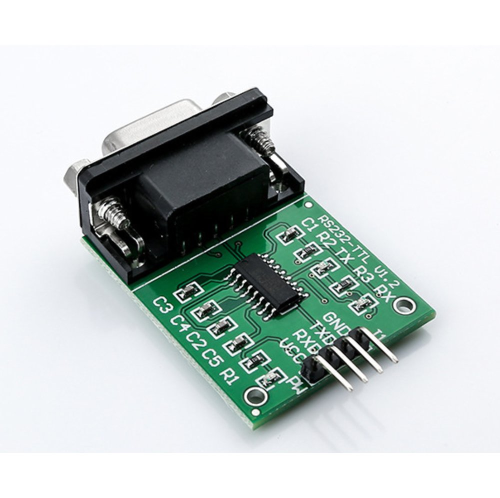 The Envistia MAX232 RS232 to TTL converter module allows you to easily interface devices using RS232 serial communication with TTL-level devices, such as microcontrollers. This module converts RS232 signals from a computer’s serial COM port to TTL logic levels (0-5V or 0-3.3V), enabling seamless communication between your computer and microcontrollers like PIC, Atmel, and others.
Features
- RS232 to TTL Conversion: Converts RS232 signals to TTL logic levels for easy interfacing with microcontrollers.
- SP3232 Transceiver IC: Utilizes the SP3232 IC, offering lower power consumption and a wider voltage support (3.3V-5V) compared to the standard MAX232 IC. See the included SP3232 datasheet below for detailed specifications.
- DB9 Female Connector: Equipped with a standard DB9 female connector for easy connection to computers and other RS232 devices.
- LED Indicators: Includes Power, RX (Receive), and TX (Transmit) LEDs for visual indication of module status and data transfer.
- Wide Compatibility: Compatible with any microcontroller (PIC, Atmel, etc.) or system with TTL serial communication capabilities.
Module Specifications
- Board Dimensions (excluding connectors): 40 x 31 mm (1.6 x 1.2 inches)
- Dimensions including connectors: 52 x 31 x 14 mm (2.0 x 1.2 x 0.55 inches)
- Working Voltage: 3.3V – 5V DC
- Working Current: ~6mA
- Power Supply: External
- Interface: TXD, RXD, GND, VCC
- Indicators: LEDs for Power, RX, and TX
Pinout and Connections
The module provides the following pins for connection:
- VCC: Power supply input (3.3V – 5V DC).
- GND: Ground connection.
- TXD: TTL Transmit Data. Connect this pin to the RX pin of your microcontroller.
- RXD: TTL Receive Data. Connect this pin to the TX pin of your microcontroller.
- DB9 Female Connector: Standard RS232 serial port connector. Connect to your computer’s serial port using a DB9 serial cable.
Using the MAX232 Module
Connecting the Module
- Power Supply: Connect the VCC and GND pins to a stable 3.3V or 5V DC power supply.
- Microcontroller Connection:
- Connect the module’s TXD pin to the RX pin of your microcontroller.
- Connect the module’s RXD pin to the TX pin of your microcontroller.
- Connect the module’s GND pin to the GND pin of your microcontroller.
- RS232 Connection: Connect the DB9 female connector to your computer’s serial port using a standard DB9 serial cable.
LED Indicators
- Power LED: Illuminates when the module is powered on.
- TX LED: Flashes when data is being transmitted from the module (TTL to RS232).
- RX LED: Flashes when data is being received by the module (RS232 to TTL).
Example Setup
Let’s say you want to send data from your computer to an Arduino Uno using the MAX232 module.
- Connect the VCC and GND pins of the module to the 5V and GND pins of the Arduino Uno, respectively.
- Connect the module’s TXD pin to the Arduino’s digital pin 0 (RX).
- Connect the module’s RXD pin to the Arduino’s digital pin 1 (TX).
- Connect the DB9 connector to your computer’s serial port.
- Upload the following sample Arduino code:
void setup() {
  Serial.begin(9600); // Initialize serial communication at 9600 baud rate
}

void loop() {
  if (Serial.available() > 0) {
    char data = Serial.read(); // Read incoming data
    Serial.print("You sent: ");
    Serial.println(data);
  }
}
- Open the Serial Monitor in the Arduino IDE.
- Type some text in the Serial Monitor and press Send.
- You should see the text you sent displayed in the Serial Monitor. The TX and RX LEDs on the module should blink as data is transmitted and received.
Troubleshooting
- No Power LED:
- Verify the power supply voltage is within the specified range (3.3V – 5V).
- Check the polarity of the power supply connection.
- No Data Transmission/Reception:
- Double-check the TXD and RXD connections between the module and the microcontroller. Ensure they are not reversed.
- Verify the baud rate settings on your computer and microcontroller are the same.
- Ensure the serial cable is properly connected to both the computer and the module.
- Check the SP3232 datasheet to make sure your application is within the IC’s specifications.
- Intermittent Communication:
- Check for loose connections.
- Ensure the power supply is stable and provides sufficient current.
Important Notes
- Always double-check your connections before applying power.
- Be careful not to exceed the voltage limits of the module or connected devices.
- Refer to the SP3232 datasheet for detailed electrical characteristics and specifications.
SP3232 Datasheet
Please refer to the attached SP3232.pdf for the complete datasheet of the SP3232 transceiver IC used in this module. This datasheet provides detailed information on the IC’s electrical characteristics, pin configurations, and application circuits.
SIPEX SP3232 DATASHEET (PDF, CLICK TO DOWNLOAD)
Where to Buy the MAX232 RS232 to TTL DB9 Female Serial Port Converter Module
MAX232 RS232 to TTL DB9 Female Serial Port Converter Module on the Envistia Mall website:
One Piece: https://envistiamall.com/products/rs232-db9-to-ttl-max232-converter-module
5-Piece Pack: https://envistiamall.com/products/max232-rs232-to-ttl-db9-female-serial-converter-with-led-indicators-pack-of-5
Copyright © 2025 Envistia Mall
EM-COMMS-0013