
Search for your product name or keyword
TL072 High-Impedance Guitar & Microphone Preamp Module User Manual
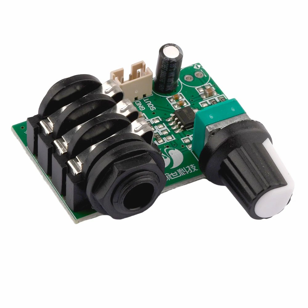 The TL072 High-Impedance Guitar Preamp Module is a compact audio preamplifier designed for electric guitars, bass guitars, and other high-impedance instruments, as well as microphones. Built around the Texas Instruments TL072 dual JFET operational amplifier, it provides clean signal amplification with low noise.
Key Features
- High Input Impedance: 1MΩ – ideal for passive pickups
- Fixed Gain: 10x amplification (20dB)
- Single Supply Operation: +9V to +15V DC (typically 12V)
- Low Noise: JFET input stage minimizes noise
- Compact Design: Easy integration into pedals and instruments
Technical Specifications
Electrical Characteristics
| Parameter | Specification |
|---|---|
| IC Chip | TL072CP (Dual JFET Op-Amp) |
| Power Supply | +9V to +15V DC (single positive supply only) |
| Recommended Voltage | +12V DC |
| Current Consumption | 5-10mA |
| Input Impedance | 1MΩ |
| Voltage Gain | 10x (20dB) fixed |
| Frequency Response | 20Hz – 20kHz |
| Input Noise | <10µV typical |
| THD | <0.01% @ 1kHz |
| Maximum Input Level | ~1Vrms before clipping |
| Output Impedance | <100Ω |
Pin Configuration
3-Pin Header
- +VCC/+V: Positive power supply (+9V to +15V)
- GND: Ground/common reference, shared with +VCC and VOUT
- VOUT: Audio signal output (low impedance)
1/4″ Input Jack
- Audio input, connect to jack tip (signal) and sleeve (ground)
Single-Supply Operation
Important: This module operates on single positive voltage only (not dual ±V supplies).
- Circuit creates “virtual ground” at approximately half supply voltage
- Input/output signals are AC-coupled via capacitors
- DC blocking prevents DC offset from affecting connected equipment
Power Supply Requirements
Voltage & Current
- Minimum: +9V DC
- Recommended: +12V DC
- Maximum: +15V DC
- Current: 5-10mA typical, 15mA maximum
Power Supply Options
For Guitar Pedals:
- 9V battery (6F22/PP3)
- 9V or 12V DC wall adapter
- Regulated power supply (preferred for lowest noise)
For Instrument Integration:
- 9V battery compartment
- Internal regulated supply from instrument’s existing power
Power Quality
- Use regulated DC supplies for best performance
- For additional filtering, add 100µF electrolytic + 100nF ceramic capacitors across power pins
- Avoid noisy switching supplies without proper filtering
⚠️ Polarity Warning
CRITICAL: Verify power supply polarity before connecting! Reverse polarity will permanently damage the TL072 IC.
Installation Guide
Installation Steps
Step 1: Power Connection
- Connect ground first – solder black wire to GND
- Connect positive supply – solder red wire to VCC/+V
- Add bypass capacitors if not present (optional):
- 100µF electrolytic (+ to VCC, – to GND)
- 100nF ceramic (parallel)
Step 2: Input Connection
- Use shielded cable for input
- Connect signal wire to 1/4″ jack input, jack tip (signal) and sleeve (ground)
- Connect shield to ground at input end only
- Keep input wiring short
Step 3: Output Connection
- Use shielded cable for output
- Connect signal wire to VOUT pin
- Connect shield to ground
- Route away from power wiring
Step 4: Testing
- Visual inspection: Check solder joints
- Continuity test: Verify no shorts between power rails
- Power test: Measure voltage at VCC pin
- Signal test: Input test signal and verify output
Operation
Signal Flow & Gain
The module provides fixed 10x gain amplification:
- Input: 100mV → Output: 1V
- Input: 50mV → Output: 500mV
- Input: 10mV → Output: 100mV
Adjust the onboard potentiometer for appropriate volume level. Note that the potentiometer adjusts the output level, not the gain.
Typical Pickup Levels (After 10x Gain)
- Single-coil: 50-150mV → 500mV-1.5V
- Humbucker: 150-500mV → 1.5V-5V (may clip)
- Active: 200-1000mV → 2V-10V (will clip)
Headroom
With 12V supply, maximum clean output is 8-10V peak-to-peak.
To avoid clipping:
- Reduce input from high-output pickups
- Use volume control before preamp
- Consider 9V supply for hot pickups
Frequency Response
Flat response across full audio spectrum (20Hz-20kHz) – no tonal coloration.
Applications
Guitar Pedal Building
- Clean Boost: 10x gain for driving amp/pedals
- Buffer: High-Z input prevents tone loss
- Preamp: Amplify weak signals before effects
Instrument Modification
- Passive Guitar/Bass: Install in cavity with 9V battery
- Acoustic Guitar: Amplify piezo pickup signals
- Vintage Instruments: Add modern output levels
Recording
- DI Enhancement: Boost signal before audio interface
- Re-amping: Amplify recorded tracks for re-amping
Other Uses
- Headphone Amp Driver: Boost for headphone amps
- Contact Mic Preamp: Amplify piezo elements
- Multi-Effects Input: Optimize levels for digital effects
Troubleshooting
No Output Signal
Check:
- Power supply voltage and polarity
- Input/output wire continuity
- Solder joints for breaks
- TL072 IC for damage
Distorted Output
Causes:
- Input overload – reduce input level
- Insufficient supply voltage – increase to 12V
- Output clipping – reduce gain or input
Excessive Noise/Hum
Solutions:
- Verify star grounding configuration
- Use shielded cables for all audio
- Add/increase power supply filtering
- Ground cable shields at one end only
- Keep audio wiring away from power
Weak Output
Check:
- Power supply voltage (should be 9-15V)
- Battery condition
- Resistor values in gain network
- Replace TL072 if weak
Diagnostic Tests
- Power: Measure VCC (should be +9V to +15V)
- DC Bias: Input/output should be ~half supply voltage
- Signal: Inject 100mV, expect ~1V output
- Frequency: Sweep 20Hz-20kHz, maintain 10x gain
Safety Guidelines
Electrical Safety
⚠️ Before working:
- Disconnect power
- Discharge capacitors
- Verify power is off
⚠️ Installation:
- Never exceed +15V DC
- Verify polarity before connecting
- Avoid short circuits
Component Handling
- TL072 is static-sensitive – use anti-static precautions
- Solder at 300-350°C, minimize time on pins
- Consider IC socket for easy replacement
Audio Safety
- Test at low volumes initially
- Gradually increase to desired level
- Protect hearing and equipment from sudden loud signals
Where to Buy the TL072 High-Impedance Guitar & Microphone Preamp Module
TL072 High-Impedance Guitar & Microphone Preamp Module at Envistia Mall
Disclaimer
This user manual is provided for informational purposes only. The manufacturer and Envistia LLC (dba Envistia Mall) are not responsible for any damages or losses resulting from the use of this product. Always exercise caution when working with electronic components.
Copyright © 2026 Envistia Mall
www.envistiamall.com
TL072
P/N EM-AUDIO-0023