
Search for your product name or keyword
NE555 Duty Cycle Adjustable Pulse Frequency Square Wave Signal Generator Module
 This NE555 square wave pulse generator module can be used to produce square wave signals for experimental development, or in applications such as driving stepper motors, and as an adjustable pulse for microcontroller (MCU) applications.
Only 31mm x 22mm (1.2″ x 0.9″), the board features an NE555 timer chip with jumpers and a potentiometer to fine-tune the frequency in four frequency ranges, and a second potentiometer to adjust the duty cycle (the relationship of how long the output is driven HIGH versus driven LOW). For example, a 50% duty cycle means the output is high 1/2 the time, and low 1/2 the time.
The input voltage to the module (VCC) is variable from 5V to 15V DC and draws approximately 15mA at 5V (35mA at 12V) with an output amplitude of 4.2V peak-to-peak to 11.4V peak-to-peak based on the supply voltage.
An indicator LED illuminates on a low-level output and flashes relative to the output frequency. At higher frequencies, the LED will appear to be on solid and without a visible flash since the flashing is too fast to see.

NE555 Module Features & Operation:
- Size: 31mm * 22mm(1.2″ x 0.9″)
- Main chip: NE555
- Input Voltage (VCC): 5V-15VDC
- Input current:~100MA
- Output amplitude: 4.2V V-PP to 11.4V V-PP. (Varies with VCC voltage)
- Maximum output current: 15MA (VCC=5V, V-PP greater than 50%), 35MA (VCC=12V, V-PP greater than 50%).
- Output LED indicator (low level, LED is on, high level, LED is off; LED flashes with frequency. When the frequency is higher than about 30Hz, the LED will appear to be always on since the blinking is too fast to see.
- There is a 4-row x 2-pin header that provides jumper settings to select different frequency ranges. The jumper connects different value capacitors in the circuit to change the RC time constant of the circuit. The multi-turn potentiometer near the frequency range jumper provides fine control over the frequency once the range is set.
- Jumper settings are:
- ~1Hz ~ 40Hz
- ~40Hz ~ 500Hz
- ~500Hz ~ 40kHz
- 40kHz ~ >200kHz
- The jumper ranges will vary between modules depending on the tolerances of the components used.
- The output duty cycle can fine-tuned using the onboard potentiometers. Duty cycle and frequency are not separately adjustable; adjusting the duty cycle will change the frequency.
- The output frequency and duty cycle are adjusted using the following variables:
- Period T = 0.7 (RA +2 RB) C
- RA, RB are 0-10K Ohm adjustable potentiometers
- 1Hz ~ 50Hz: C = 0.001UF
- 50Hz ~ 1kHz: C = 0.1UF
- 1KHz ~ 10kHz: C = 1UF
- 10kHz ~ 200kHz: C = 100UF
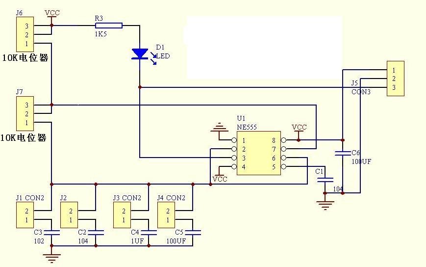
Module Schematic
Copyright © 2016-2022 Envistia Mall
www.envistiamall.com
P/N EM-OTHER-0004