
Search for your product name or keyword
2-Channel 5V PWM Pulse / Square Wave Generator Module
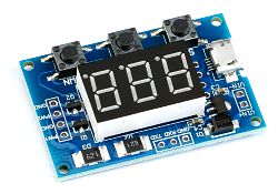 This 2-channel PWM pulse / square wave generator provides two pulse / square wave outputs with independent control over each channel’s duty cycle and frequency using the straightforward LED display and set/up/down buttons. It can also be programmed through its serial RS-232 interface.
Applications for the module include:
- A square wave generator to generate square wave signals for experimentation and control
- Driving stepper motors
- Generating adjustable pulses for microcontroller use
- Generating adjustable pulses for PWM control of lighting and LEDs
Features and Specifications
- The frequency and duty cycle for each channel can be set individually
- Operating Voltage: 5-30V, supports MicroUSB 5V input power
- Frequency Range: 1Hz – 150KHz
- Frequency Precision: 2%
- Output Signal Capacity: Up to 30mA output current
- Output Voltage: Same as input voltage, or can be independently varied from 5V to 30V with an external power supply input (see “Changing The Output Voltage” below
- Ambient Operating Temperature: -30℃ to 70℃
Operating Parameter Settings
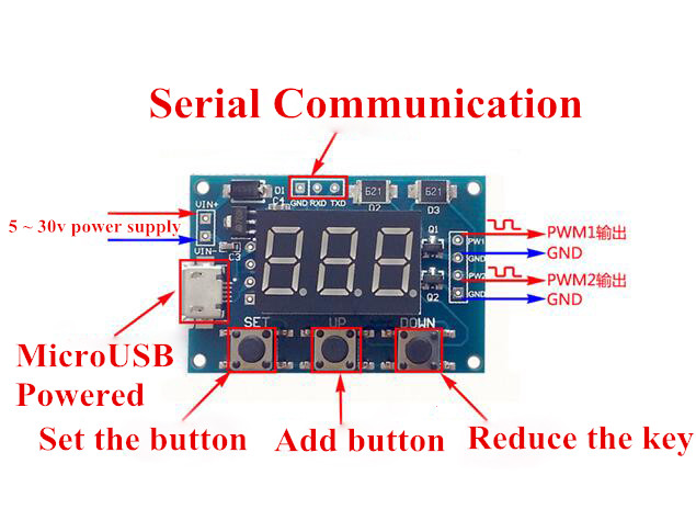
The module has 3 control buttons: Set, Up, and Down
This module has two different versions of firmware depending upon its manufacturer. The specifications and operating parameters are the same for both versions, but the procedures to change the frequency and duty cycle for each version are slightly different.
When you power on the module, if the display shows “FR1” or “FA1”, please follow the instructions below to operate the module:
Short pressing the SET key will step the display through the 4 operating parameter values:
- FR1 (or FA1): PWM1 frequency
- dU1: PWM1 duty cycle
- FR2 (or FA2): PWM2 frequency
- dU2: PWM2 duty cycle
When each parameter is selected by pressing the SET button, the parameter name will flash before displaying the value.
After the parameter is selected, press the UP and DOWN buttons to modify the parameter’s value.
The duty cycle can be set from 1% to 100% in 1% increments.
The frequency range can be selected before entering the value by long-pressing the SET button (approximately 1 second or longer):
XXX Display (Default): Frequency values from 1Hz – 999Hz frequency range
XX.X Display (1 long press of the SET button): 0.1Khz – 99.9Khz frequency range
(i.e. 01.2 = 1.2KHz, 55.5 = 55.5KHz)
X.X.X. Display (2 long presses of the SET button):1Khz~150Khz frequency range
(i.e. 0.3.5. = 3.5KHz, 1.0.0. = 100KHz)
When you power on the module, if the display shows a number (the PA1 duty cycle), please follow the instructions below to operate the module:
Short pressing the SET key will step the display through the 4 operating parameter values:
- PA1: PWM1 frequency
- dU1: PWM1 duty cycle
- PA2: PWM2 frequency
- dU2: PWM2 duty cycle
To change a parameter, press and hold the SET button, and the first parameter name (i.e. PA1, dU1, etc.) will briefly display, followed by the flashing value of the parameter. Tap the UP and DOWN buttons to change the value. Then press and hold the SET button to save the changed parameter and proceed to the next parameter. After scrolling through all four parameters, the final long press of the SET button will return you to the power-on display showing the saved parameter values.
The duty cycle can be set from 1% to 100% in 1% increments.
While you are in the frequency settings PA1 or PA2, the frequency range can be selected before entering the value by short-pressing (tapping) the SET button:
XXX Display (Default): Frequency values from 1Hz – 999Hz frequency range
X.XX Display (1 short press of the SET button): 10hz – 9.99Khz frequency range
(i.e. 1.20 = 1.2KHz, 5.55 = 5.55KHz)
XX.X Display (2 short presses of the SET button): 100hz – 99.9Khz frequency range
(i.e. 01.2 = 1.2KHz, 55.5 = 55.5KHz)
XXX. Display (3 short presses of the SET button): 1Khz~150Khz frequency range
(i.e. 003. = 3KHz, 100. = 100KHz)
Changing the Output Voltage
The output voltage level is normally the same as the input voltage (nominally 5V). This can be changed by applying an external DC power supply of the desired voltage, separate from the 5V support power supply, to the pads on the back side of the board, and cutting the trace as shown in the drawing at right. The voltage of the DC power supply will then set the output voltage.

Serial Port RS-232 Control
- Communication Standard:
- 9600 bps
- Data Bit: 8
- Stop Bit: 1
- Verify Bit: None
- Flow Control: None
Setting PWM Frequency via the Serial Port
- “S1FXXXT”:set PWM1 frequency as XXX HZ (001~999)
- “S1FXX.XT”:set PWM1 frequency as XX.X KHZ (00.1~99.9)
- “S1F:X.X.X.T”:set PWM1 frequency as XXX KHZ (0.0.1.~1.5.0.)
- “S1”: PWM1
- “S2”: PWM2
- “F”: Frequency
- “D”: Duty cycle
- “T”: Stop sign bit
Setting PWM Duty Cycle via the Serial Port
- “S1DXXXT”:set PWM1 duty cycle as XXX;(001~100)
- “S2DXXXT”:set PWM2 duty cycle as XXX;(001~100)
Setting successfully back: DOWN
Setting unsuccessfully back: FALL
Other Resources
Testing a Dual Channel Signal Generator (#71) by Martyn Davies on Youtube:
Copyright © 2017-2024 Envistia Mall
www.envistiamall.com
P/N EM-OTHER-0010