
Search for your product name or keyword
L293D Motor Drive Shield For Arduino Uno & MEGA2560 User Guide
 This document provides a comprehensive guide to using the Envistia Mall L293D Motor Drive Shield with Arduino Uno, MEGA2560, and Duemilanove boards. This shield allows you to control up to four DC motors or two stepper motors, making it ideal for robotics projects and other motor control applications. This manual assumes the user has a basic understanding of Arduino and electronics.
Product Overview
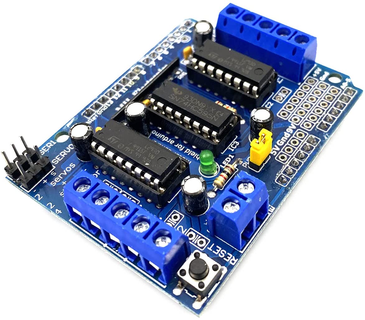
The L293D Motor Drive Shield is an expansion board designed to interface with Arduino microcontrollers. It utilizes the L293D motor driver IC, which provides the necessary current and voltage to drive motors. The shield simplifies motor control by providing convenient terminals and connections for motors and power supplies.
Key Features
- Motor Control:
- Control up to 4 bidirectional DC motors.
- Control up to 2 stepper motors (unipolar or bipolar).
- PWM Speed Control: 4 PWM channels for speed control of DC motors (approximately 0.5% resolution).
- L293D H-Bridge: Uses the L293D chip, providing 0.6A continuous current (1.2A peak) per bridge.
- Voltage Range: Operates with motor voltages from 4.5V to 36V.
- Protection: Built-in thermal shutdown protection.
- Pull-Down Resistors: Ensures motors are stopped during power-up.
- Easy Wiring: Features two large terminal block connectors for easy motor wiring (10-22AWG).
- Power Supply Options: Removable jumper for selecting a single or dual power supply configuration.
- Compatibility: Compatible with Arduino Uno, MEGA2560, and Duemilanove.
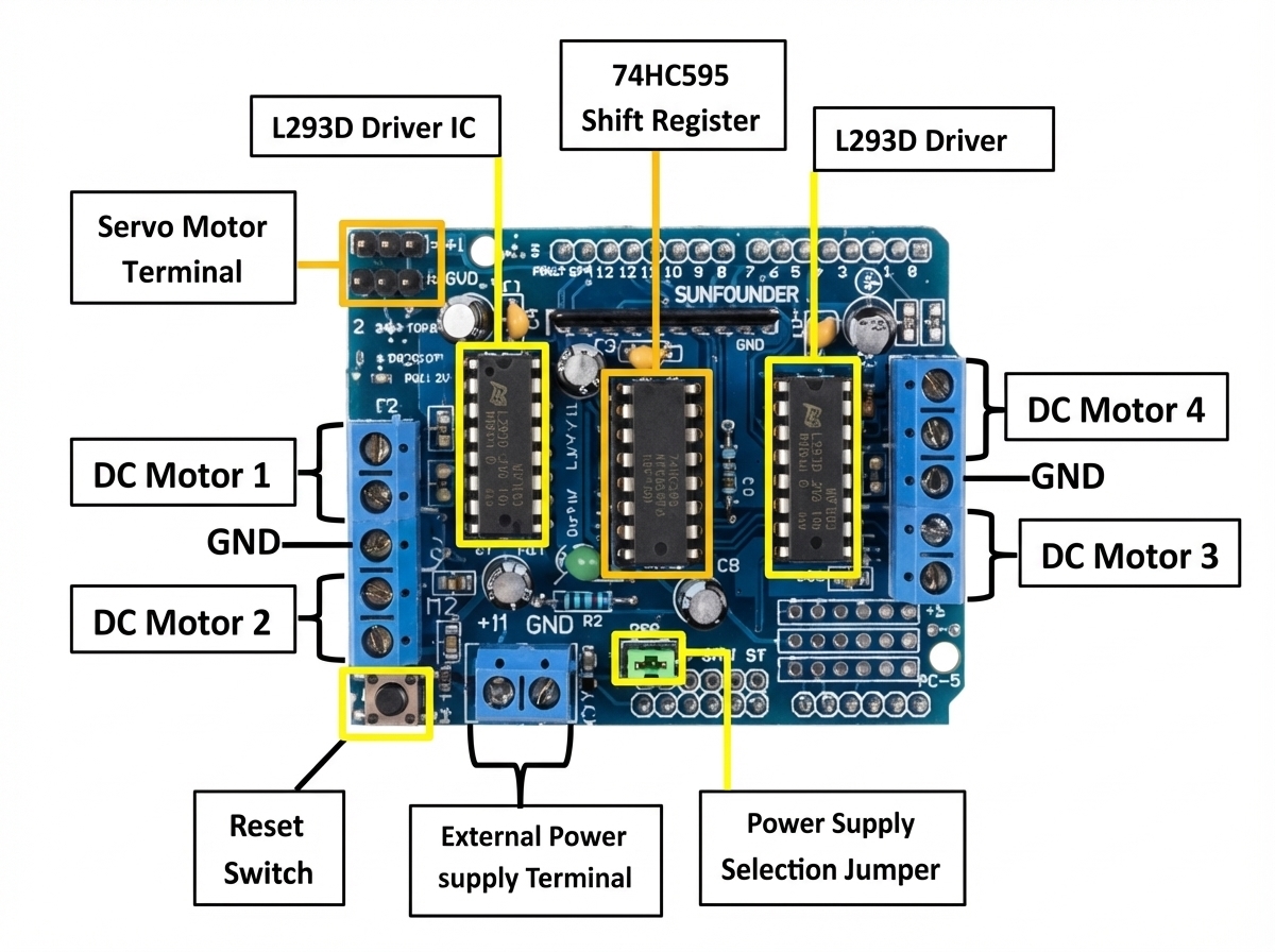
- Shift Register: Includes a 74HC595 shift register to expand Arduino’s digital pins.
- Reset Button: Includes a reset button that mirrors the Arduino’s reset button.
Hardware Setup
Shield Installation
- Power Off: Ensure your Arduino board is powered off before installing the shield.
- Alignment: Align the shield’s pins with the corresponding headers on the Arduino board.
- Secure Connection: Gently press the shield onto the Arduino board until all pins are firmly seated.
Motor Connections
The shield provides two terminal blocks for connecting motors:
- Terminal Block 1: Used for connecting Motor 1 (M1) and Motor 2 (M2).
- Terminal Block 2: Used for connecting Motor 3 (M3) and Motor 4 (M4).
Each motor connection has two terminals. Connect the motor wires to these terminals, ensuring a secure connection. Use wire gauges between 10 and 22 AWG.
Stepper Motor Connections
The shield can control two stepper motors. The connections are as follows:
- Motor 1 (M1): Can be used for one stepper motor.
- Motor 3 (M3): Can be used for a second stepper motor.
Refer to the stepper motor’s datasheet for the correct wiring configuration.
Power Supply Connections
The shield offers flexible power supply options:
- Single Power Supply (Arduino and Motors): With the jumper installed, the Arduino’s 5V power supply is used to power the L293D logic. The motor power is supplied via the Vin pin of the Arduino.
- Dual Power Supply (Separate Arduino and Motor Power): Remove the jumper. Connect the Arduino to its own power supply (e.g., via USB). Connect a separate power supply (4.5V – 36V) to the
EXT_PWRterminal block. Important: Ensure the ground of both power supplies are connected.
EXT_PWR Terminal Block:
- +: Positive voltage supply for motors (4.5V to 36V).
- -: Ground (GND) for the motor power supply.
Important Notes:
- Voltage: Ensure the motor voltage does not exceed the maximum voltage rating of the L293D (36V).
- Current: Do not exceed the maximum current rating of the L293D (0.6A continuous, 1.2A peak per bridge).
- Polarity: Double-check the polarity of your power supply connections.
- Ground: When using separate power supplies, ensure that the grounds are connected.
Servo Connections
The shield provides a 3-pin header for connecting servos. The pins are labeled SERVO.
SIG: Signal pin5V: 5V powerGND: Ground
Pin Assignments
The L293D Motor Drive Shield uses the following Arduino pins:
| Motor Control | Arduino Pin |
|---|---|
| Motor 1 Enable (PWM) | 9 |
| Motor 1 Forward | 2 |
| Motor 1 Backward | 3 |
| Motor 2 Enable (PWM) | 10 |
| Motor 2 Forward | 4 |
| Motor 2 Backward | 5 |
| Motor 3 Enable (PWM) | 11 |
| Motor 3 Forward | 6 |
| Motor 3 Backward | 7 |
| Motor 4 Enable (PWM) | 12 |
| Motor 4 Forward | 8 |
| Motor 4 Backward | 13 |
Note: These pin assignments are fixed and cannot be changed without modifying the shield hardware.
Motor Connections
- M1, M2: Connect a DC motor or one coil of a stepper motor.
- M3, M4: Connect a DC motor or the other coil of a stepper motor.
Powering the Shield
The L293D Motor Drive Shield can be powered in two ways:
- Single Power Supply (Jumper Installed): In this configuration, the Arduino and the motors share the same power supply. The Arduino is powered through the USB port or a power adapter, and the motors are powered through the Arduino’s 5V or Vin pin. Important: Ensure that the power supply can provide enough current for both the Arduino and the motors. This is generally suitable for small motors with low current requirements.
- Separate Power Supplies (Jumper Removed): In this configuration, the Arduino and the motors have separate power supplies. This is the recommended configuration for larger motors or when using a higher voltage for the motors. Connect the motor power supply to the terminal block labeled
EXT_PWR. The voltage should be between 4.5V and 36V. The Arduino can be powered separately via USB or a DC power adapter.
To select the power configuration:
- Locate the jumper labeled
EXT_PWR. - For a single power supply: Place the jumper to connect the two pins.
- For separate power supplies: Remove the jumper.
Software Setup
Arduino IDE
Ensure you have the Arduino IDE installed on your computer. You can download it from the official Arduino website: https://www.arduino.cc/en/software
Arduino IDE Libraries
No specific libraries are required to use the L293D Motor Drive Shield. You can control the motors directly using digital output pins and PWM. However, using a library can simplify the code and make it more readable. Consider using a general-purpose motor control library if you prefer.
Basic Control Example (DC Motor)
This example demonstrates how to control a single DC motor connected to Motor 1 (M1).
// Define motor control pins
const int motor1_enable = 9;  // PWM pin for speed control
const int motor1_forward = 2;
const int motor1_backward = 3;

void setup() {
  // Set pin modes
  pinMode(motor1_enable, OUTPUT);
  pinMode(motor1_forward, OUTPUT);
  pinMode(motor1_backward, OUTPUT);
}

void loop() {
  // Rotate motor forward at half speed
  digitalWrite(motor1_forward, HIGH);
  digitalWrite(motor1_backward, LOW);
  analogWrite(motor1_enable, 127); // 0-255 (0 = stopped, 255 = full speed)
  delay(2000);

  // Rotate motor backward at full speed
  digitalWrite(motor1_forward, LOW);
  digitalWrite(motor1_backward, HIGH);
  analogWrite(motor1_enable, 255);
  delay(2000);

  // Stop the motor
  digitalWrite(motor1_forward, LOW);
  digitalWrite(motor1_backward, LOW);
  analogWrite(motor1_enable, 0);
  delay(2000);
}
Explanation:
- Pin Definitions: Defines the Arduino pins connected to the motor control signals.
setup()Function: Sets the pin modes asOUTPUT.loop()Function:digitalWrite()controls the direction of the motor. Settingmotor1_forwardHIGH andmotor1_backwardLOW rotates the motor in one direction. The opposite rotates it in the other direction. Setting both LOW stops the motor.analogWrite()controls the motor speed using PWM. Values range from 0 (stopped) to 255 (full speed).delay()pauses the program execution for a specified time.
Stepper Motor Control
Controlling stepper motors requires a more complex code structure to manage the stepping sequence. Refer to stepper motor datasheets and Arduino stepper motor examples for detailed code implementations. You can use the same digital pins as the DC motors, but you’ll need to control the sequence of HIGH/LOW signals to achieve the desired stepping.
Troubleshooting
- Motor Not Running:
- Check power supply connections and voltage.
- Verify motor wiring.
- Ensure the enable pin is set HIGH (for PWM control).
- Check the code for errors.
- Motor Running in the Wrong Direction:
- Swap the motor wires.
- Reverse the logic in your code.
- Arduino Not Responding:
- Ensure the shield is properly seated on the Arduino.
- Check for short circuits.
- Verify the Arduino is powered correctly.
- Overheating:
- Reduce the motor voltage or current.
- Ensure the motor is not overloaded.
- Consider using a heatsink on the L293D chip.
Safety Precautions
- Always disconnect the power supply before making any connections or modifications.
- Do not exceed the maximum voltage and current ratings of the L293D.
- Ensure proper ventilation to prevent overheating.
- Be careful when working with electrical components.
Where to Buy the L293D Motor Drive Shield for Arduino
L293D Motor Drive Shield Expansion Board For Arduino on the Envistia Mall website.
Further Resources
- Arduino website: https://www.arduino.cc/
- How to Control DC, Servo, and Stepper Motors with L293D Motor Driver Shield & Arduino on playwithcircuit.com.
- L293D datasheet: Search online for the L293D datasheet for detailed technical information.
- Online Arduino communities and forums.
The L293D Motor Drive Shield is a versatile tool for controlling DC and stepper motors with your Arduino. By following this guide, you should be able to successfully set up and use the shield in your projects. Remember to always observe safety precautions and consult the datasheets for the L293D and your motors for detailed specifications.
Disclaimer
This user manual is provided for informational purposes only. The manufacturer and Envistia LLC (dba Envistia Mall) are not responsible for any damages or losses resulting from the use of this product. Always exercise caution when working with electronic components.
Copyright © 2026 Envistia Mall
www.envistiamall.com
L293D
P/N EM-SHIELD-0022