
Search for your product name or keyword
DY-SV5W Voice Playback MP3 Music Player Amplifier Module User Manual
Introduction
 The DY-SV5W is an intelligent and versatile voice playback module designed for a wide range of audio applications. This module offers multiple control methods, including I/O triggering, UART serial port control, and ONE_line single bus serial port control, providing flexibility in your projects.
With an onboard 5W Class D amplifier, it can directly drive 4Ω 3-5W speakers, delivering clear and powerful audio output. It supports MP3 and WAV decoding formats and can accommodate up to 32GB TF card memory. Audio files can be easily updated on the TF card by connecting the module to a computer via USB.
The module also features a 3.5mm audio interface, a U disk interface, a Micro USB download interface, and button mode for added convenience.
The module can:
Play up to 255 tracks via simple I/O trigger control
- Play up to 65,535 tracks via UART serial commands
- Be controlled via a ONE_line single‑wire serial protocol
- Be used as a standalone MP3 player with front‑panel buttons
Audio is stored on a TF (MicroSD) card or USB flash drive, and can be updated easily via the onboard Micro USB connector.
Key Features
- Audio formats: MP3, WAV
- Sampling rates: 8 / 11.025 / 12 / 16 / 22.05 / 24 / 32 / 44.1 / 48 kHz
- Audio quality: 24‑bit DAC, dynamic range ≈ 90 dB, SNR ≈ 85 dB
- Storage:
- Supports FAT16 / FAT32 file systems
- Up to 32 GB TF card and 32 GB USB flash drive
- Amplifier:
- Onboard 5 W Class‑D amplifier
- Drives 4–8 Ω speakers, recommended 4 Ω 3–5 W
- Control methods:
- I/O trigger modes (combination & stand‑alone)
- UART (9600 bps, 8‑N‑1)
- ONE_line single‑wire serial
- Standard MP3 button mode (front‑panel keys)
- Operating modes:
- Selectable via 3‑bit DIP switch (7 modes total)
- Status output:
- BUSY pin: low during playback, high when idle
- Supply:
- 5 V DC
Hardware Overview
Board Connectors and Interfaces
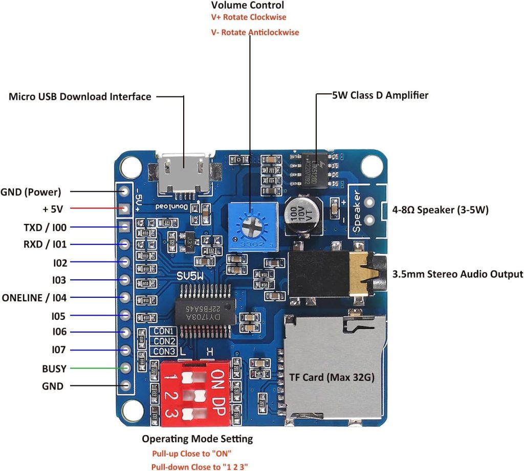
Typical DY‑SV5W modules provide:
- Power input
- VCC: +5 V DC
- GND: Ground
- Speaker output
- 2‑pin screw terminal or solder pads to connect a 4–8 Ω speaker (3–5 W)
- Audio line‑out
- 3.5 mm audio jack for headphones or external amplifier (if present on your board variant)
- Storage / USB
- TF (MicroSD) slot for up to 32 GB card
- USB‑A / U‑disk connector for USB flash drive (if present)
- Micro USB for connecting to a PC to update audio files on the TF card
- Control I/O header
- Pin header for: VCC, GND, TXD/IO0, RXD/IO1, IO2…IO7, ONE_LINE, BUSY
- DIP Switch
- 3‑position DIP used to select one of 7 operating modes
Electrical Specifications (Summary)
- Supply voltage: 5 V DC
- I/O voltage levels:
- Input low (VIL): 0–0.8 V
- Input high (VIH): 2.7–3.3 V
- Output low (VOL): 0–0.33 V
- Output high (VOH): 2.7–3.3 V
- UART interface:
- Baud: 9600 bps
- Data bits: 8
- Stop bits: 1
- Parity: None (N)
Note: I/O pins are 3.3 V logic. When driving from a 5 V MCU, use proper level shifting or series resistors if needed.
Pinout Description
| Pin | Function (by mode) |
|---|---|
| VCC | +5 V power input |
| GND (PWR) | Power ground |
| TXD / IO0 | IO0 in I/O trigger modes; TXD (module TX → MCU RX) in UART mode |
| RXD / IO1 | IO1 in I/O trigger modes; RXD (module RX ← MCU TX) in UART mode |
| IO2 | IO2 in I/O trigger modes |
| IO3 | IO3 in I/O trigger modes |
| IO4 / ONE_LINE | IO4 in I/O trigger modes; ONE_line RX in ONE_line mode |
| IO5 | IO5 in I/O trigger modes |
| IO6 | IO6 in I/O trigger modes |
| IO7 | IO7 in I/O trigger modes |
| BUSY | 0 V (LOW) during playback; 3.3 V (HIGH) when playback has ended |
| GND | Signal reference ground |
Operating Modes and DIP Switch
The 3‑bit DIP switch (CON1, CON2, CON3) selects the control mode:
- Each switch has two positions:
- Pull‑down (toward the number “1/2/3”) = logic 0
- Pull‑up (toward “ON”) = logic 1
Mode Table
| Mode name | CON3 | CON2 | CON1 | Description |
|---|---|---|---|---|
| I/O Combination Mode 0 | 0 | 0 | 0 | 8 inputs form binary combination to select up to 255 tracks (edge‑triggered) |
| I/O Combination Mode 1 | 0 | 0 | 1 | Same combinations, but level‑triggered (continuous low = loop) |
| I/O Stand‑alone Mode 0 | 0 | 1 | 0 | IO0–IO7 each trigger one dedicated track, edge‑triggered |
| I/O Stand‑alone Mode 1 | 0 | 1 | 1 | IO0–IO7 each trigger one track, level‑triggered |
| UART Control Mode | 1 | 0 | 0 | Controlled via UART (TXD/RXD) |
| ONE_Line Mode | – | – | – | ONE_line single‑wire serial on IO4/ONE_LINE (board‑specific DIP combination) |
| Standard MP3 Mode | 1 | 0 | 1 | Front‑panel MP3 button mode (PREV/V−, NEXT/V+, P/P/MODE, EQ, RPT) |
Exact DIP mapping for ONE_Line vs Standard MP3 mode depends on the PCB printing. Use the table printed on your board or datasheet to confirm.
Preparing Audio Files
File System and Media
- Use TF (MicroSD) card or USB flash drive
- Format as FAT16 or FAT32
- Capacity up to 32 GB
File Naming Rules
IMPORTANT: The module relies on numeric file names to map I/O or serial commands to tracks.
- For I/O Combination and stand‑alone modes:
- Use 5‑digit numeric names:
00001.mp3,00002.mp3, …00255.mp3
- For modes using only 8 tracks:
00001.mp3to00008.mp3
- For UART / ONE_line:
- Track numbers are logical indices; the module internally maps them to file names (according to numeric order).
- To avoid confusion, keep the 5‑digit numeric convention for all tracks.
Tip: Keep all audio files in the root folder, or follow the UART “device/path” rules if you plan to use folder‑based playback modes.
Loading Audio Files
- Insert TF card into the module’s TF card slot.
- Connect a Micro USB cable from the module to your PC.
- The TF card appears as a removable drive.
- Copy or delete audio files as needed.
- Safely eject the drive and disconnect USB.
Power and Speaker Connections
Basic Power Connection
- Connect 5 V to VCC, and GND to ground.
- Recommended supply: stable 5 V with enough current for:
- Module logic
- 5 W audio output (e.g., ≥1 A supply if driving a 4 Ω 5 W speaker loudly)
Speaker Connection
- Connect a 4 Ω 3–5 W speaker to the speaker output terminals.
- The Class‑D amplifier is bridge‑tied load (BTL):
- Do not connect any speaker terminal to ground.
- Use both outputs directly to the speaker.
Using Line‑Out (if available)
- Plug into the 3.5 mm jack to feed an external amplifier or headphones.
- Turn down volume on external amp before powering up to avoid surprises.
I/O Trigger Modes
All I/O modes use pins IO0–IO7 as digital inputs. Default idle level is HIGH (1).
I/O Combination Mode 0 (CON3=0, CON2=0, CON1=0)
Concept:
8 bits (IO7…IO0) form a binary number selecting one of up to 255 tracks.
- Trigger: falling edge from HIGH → LOW on any IO according to a pattern.
- After triggering, the MCU releases the pins back to HIGH.
- Playback:
- Module plays the selected track once.
- If retriggered during playback, it immediately starts the new track.
- If the pattern is held low, playback will loop.
Track mapping example:
| IO7 | IO6 | IO5 | IO4 | IO3 | IO2 | IO1 | IO0 | Track (file) |
|---|---|---|---|---|---|---|---|---|
| 1 | 1 | 1 | 1 | 1 | 1 | 1 | 0 | 00001.mp3 |
| 1 | 1 | 1 | 1 | 1 | 1 | 0 | 1 | 00002.mp3 |
| … | … | … | … | … | … | … | … | … |
| 0 | 0 | 0 | 0 | 0 | 0 | 0 | 0 | 00255.mp3 |
Use case:
You can connect IO pins to an MCU, switches, or sensors that present binary patterns to select tracks.
I/O Combination Mode 1 (CON3=0, CON2=0, CON1=1)
Same mapping as Mode 0, but level‑triggered:
- MCU drives IOs to the desired binary pattern and keeps them LOW during playback.
- As long as the pattern is held low, the module will loop the track.
- Releasing pins back to HIGH stops playback immediately, at any time.
I/O Stand‑Alone Mode 0 (CON3=0, CON2=1, CON1=0)
Each IO pin directly controls one track:
- IO0 →
00001.mp3 - IO1 →
00002.mp3 - IO2 →
00003.mp3 - IO3 →
00004.mp3 - IO4 →
00005.mp3 - IO5 →
00006.mp3 - IO6 →
00007.mp3 - IO7 →
00008.mp3
Behavior:
- Trigger: falling edge (HIGH → LOW) on one IO plays that track once.
- The IO returns to HIGH after triggering.
- Retiggering during playback starts the track again.
- Holding the IO low keeps the track looping.
Ideal for:
Simple buttons or switches: one input = one sound.
I/O Stand‑Alone Mode 1 (CON3=0, CON2=1, CON1=1)
Similar to Stand‑Alone Mode 0 but level‑sensitive:
- Drive IO low to start and keep looping the assigned track.
- Release IO back to HIGH to stop immediately.
BUSY Pin Usage
In all I/O modes, BUSY indicates playback state:
- LOW (0 V) → module is playing a track
- HIGH (~3.3 V) → playback finished / idle
Example uses:
- Drive an LED (via resistor and transistor if needed) to show playback.
- Allow an MCU to know when it is safe to trigger another sound.
UART Control Mode
Set DIP: CON3=1, CON2=0, CON1=0
Electrical Connection
- Module TXD/IO0 → MCU RX (3.3 V logic)
- Module RXD/IO1 → MCU TX
- Common GND
Serial Parameters
- Baud: 9600
- Format: 8 data bits, no parity, 1 stop bit (8‑N‑1)
Frame Format
Each command frame:
Start (CMD_CODE) – CMD_TYPE – DATA_LENGTH – DATA bytes… – CRC
- CMD_CODE: always
0xAA - CMD_TYPE: identifies the command
- DATA_LENGTH: number of data bytes (
n) following - DATA: payload (if
n > 0) - CRC (SM): sum of all bytes from CMD_CODE to last data byte, low 8 bits only
Data is sent big‑endian for multi‑byte values (high byte first).
Core Command Summary
10.4.1 Control Commands (no response)
- Play
- Frame:
AA 02 00 AC - Pause
- Frame:
AA 03 00 AD - Stop
- Frame:
AA 04 00 AE - Previous track
- Frame:
AA 05 00 AF - Next track
- Frame:
AA 06 00 B0 - Volume +
- Frame:
AA 14 00 BE - Volume −
- Frame:
AA 15 00 BF - Previous folder
- Frame:
AA 0E 00 B8 - Next folder
- Frame:
AA 0F 00 B9 - End playing (stop any inter‑cut / insert play)
- Frame:
AA 10 00 BA
Setting Commands (no response)
- Set Volume (0–30, default 20)
- Frame:
AA 13 01 VOL SM VOL= volume step (0x00–0x1E)- Set Play Mode
- Frame:
AA 18 01 MODE SM - Modes:
00– Full cycle (play all tracks in sequence, loop)01– Single track loop02– Single stop (play once)03– Random play04– Repeat current folder05– Random in current folder06– Order in folder then stop07– Order on device then stop
- Set Cycle Times
- Frame:
AA 19 02 HighByte LowByte SM - Set EQ
- Frame:
AA 1A 01 EQ SM - EQ:
00– Normal01– POP02– ROCK03– JAZZ04– CLASSIC
- Select Specific Track by Number
- Frame:
AA 07 02 HighByte LowByte SM - Track numbers: 1–65535
- Select Device and Path
- Frame:
AA 08 Length Device PathBytes… SM - Devices:
00– USB01– SD/TF02– FLASH
- Switch to Selected Device
- Frame:
AA 0B 01 Device SM - Select Track for Inter‑cut (insert play)
- Frame:
AA 16 03 Device HighByte LowByte SM - Select Inter‑cut Path
- Frame:
AA 17 Length Device PathBytes… SM - Select File but Do Not Play
- Frame:
AA 1F 02 HighByte LowByte SM
Query Commands (with response)
- Check Play State
- Send:
AA 01 00 AB - Response:
AA 01 01 State SM00– Stop01– Playing02– Paused
- Check Device Online
- Send:
AA 09 00 B3 - Response:
AA 09 01 Device SM - Check Current Device
- Send:
AA 0A 00 B4 - Response:
AA 0A 01 Device SM - Check Total Number of Tracks
- Send:
AA 0C 00 B6 - Response:
AA 0C 02 HighByte LowByte SM - Check Current Track Number
- Send:
AA 0D 00 B7 - Response:
AA 0D 02 HighByte LowByte SM - Check First Track in Folder
- Send:
AA 11 00 BB - Response:
AA 11 02 HighByte LowByte SM - Check Number of Tracks in Folder
- Send:
AA 12 00 BC - Response:
AA 12 02 HighByte LowByte SM
ONE_line Mode (Single‑Wire Serial)
ONE_line provides a simple single‑wire control on IO4/ONE_LINE.
- Data is sent LSB first.
- A start flag low pulse (≥ 2 ms) precedes each command sequence.
Command Bytes (HEX)
| HEX | Meaning | Notes / Example |
|---|---|---|
| 00–09 | Digits 0–9 | Used for numeric entry |
| 0A | Clear digits | Clears entered numeric buffer |
| 0B | Select / Enter | Confirms the numeric entry for a function |
| 0C | Volume setting | Use digits + 0B |
| 0D | EQ setting | Use digits + 0B |
| 0E | Set cycle mode | Use digits + 0B |
| 0F | Set channel | Device selection etc. |
| 10 | Select music for inter‑cut | |
| 11 | Play | |
| 12 | Pause | |
| 13 | Stop | |
| 14 | Previous track | |
| 15 | Next track | |
| 16 | Previous directory | |
| 17 | Next directory | |
| 18 | Select SD card | |
| 19 | Select U‑disk | |
| 1A | Select FLASH | |
| 1B | System sleep | |
| 1C | End playing |
Example: Select Track 123
For track 00123.mp3:
- Send digit bytes:
0x01,0x02,0x03 - Send Select/Enter:
0x0B
The module interprets “123” and selects that track.
Example: Set Volume to 12
- Send function code for volume:
0x0C - Send digits:
0x01,0x02 - Send Select/Enter:
0x0B
Standard MP3 Button Mode
Set DIP: CON3=1, CON2=0, CON1=1
Front‑panel buttons (or header pads) provide:
- PREV / V−: previous track / volume down (long press)
- NEXT / V+: next track / volume up (long press)
- P/P / MODE: play/pause, mode change
- EQ: cycle EQ presets
- RPT: repeat mode
This mode is ideal when you want a simple standalone MP3 player without any MCU.
Typical Application Examples
Simple Door Chime (I/O Stand‑Alone Mode 0)
- Mode: I/O Stand‑Alone Mode 0
- Hardware:
- Push button connected from IO0 to GND
- IO0 has internal pull‑up via module or external resistor to 3.3 V
- Audio:
- Put
00001.mp3(chime sound) on TF card
Operation: Pressing the button momentarily pulls IO0 low → module plays 00001.mp3 once.
Multi‑Sound Panel with 8 Buttons
- Mode: I/O Stand‑Alone Mode 1
- Hardware:
- 8 buttons from IO0–IO7 to GND, each with pull‑up
- Audio:
00001.mp3→ IO0- …
00008.mp3→ IO7
Operation: Holding a button keeps its sound looping; releasing stops it.
MCU‑Controlled Effects via UART (Arduino / ESP32)
- Mode: UART Control Mode
- Hardware:
- Module TXD → MCU RX
- Module RXD → MCU TX
- GND shared
- BUSY → MCU input pin (optional)
- Software:
- Open serial at 9600, 8‑N‑1
- Use UART frames to:
- Select tracks based on event ID
- Control volume dynamically
- Query play state / track number
Synchronized Lighting using BUSY Pin
- Use BUSY to drive an MCU input or transistor controlling LEDs.
- When BUSY is low (playing), start LED animation.
- When BUSY returns high, stop the effect.
DY-SV5W Design Tips and Best Practices
- Power:
- Provide sufficient current; 5 W at 4 Ω can draw up to ~2 A peaks.
- Use decoupling capacitors near the module.
- Grounding:
- Keep audio and logic grounds common but use sensible layout to avoid noise.
- I/O Protection:
- Remember the I/O pins are 3.3 V.
- For 5 V MCUs, consider:
- Series resistors (e.g., 1–4.7 kΩ)
- Level shifters for UART and digital inputs
- Audio Files:
- Normalize audio volume in software (e.g., in Audacity) to avoid extreme differences between tracks.
- Keep bitrates reasonable (e.g., 128–192 kbps MP3) for faster indexing.
- Debugging:
- Start with Standard MP3 Mode to confirm audio and storage work.
- Then move to I/O or UART modes.
- Use BUSY and Query commands to diagnose playback logic.
Troubleshooting
| Symptom | Possible Cause / Fix |
|---|---|
| No sound at all | Check 5 V power and ground, speaker connection, correct mode |
| Plays but very quiet or distorted | Speaker impedance too high/low, supply sagging, volume low |
| No response to I/O pins | Check mode (DIP), ensure IOs idle high and pulled correctly |
| UART commands ignored | Check 9600 8‑N‑1, correct wiring (TX ↔ RX), CRC calculation |
| Card not detected | Format as FAT16/FAT32, ≤32 GB, proper file names |
| Wrong track plays | Verify numeric file naming, combination bits, or track index |
Safety and Handling
- Do not exceed 5 V supply.
- Avoid shorting speaker outputs to ground.
- Do not hot‑plug or remove the TF card while power is applied and playback is active.
- Use the module in environments within −20 °C to +85 °C and 0–95% RH non‑condensing.
Where to Buy the DY-SV5W
DY-SV5W Voice Playback MP3 Music Player Amplifier Module at Envistia Mall
Additional DY-SV5W Resources and Videos
DY-SV5W Voice Playback MP3 Music Player Amplifier Module PDF Datasheet (Click to download)
DY-SV5W MP3 Player Tutorial on the Digital Town Website
Video: Arduino C++ DY-SV5W MP3 Player with Uno or Mega 2560 Video from Digital Town:
Appendix A: UART Command Examples with CRC
In UART mode, every command frame must include a correct CRC (SM) byte.
Here is how to build common commands and calculate the CRC.
Frame Format Recap
AA [CMD_TYPE] [DATA_LENGTH] [DATA...] [SM]
AA= start byteCMD_TYPE= command codeDATA_LENGTH= number of data bytes that followDATA= payload (track number, volume, etc.)SM= low 8 bits of the sum of all bytes fromAAto lastDATAbyte
A.1 Play / Pause / Stop / Next / Previous
These are simple 4‑byte frames with no data:
| Command | Frame (hex) | SM calculation |
|---|---|---|
| Play | AA 02 00 AC | AA + 02 + 00 = AC |
| Pause | AA 03 00 AD | AA + 03 + 00 = AD |
| Stop | AA 04 00 AE | AA + 04 + 00 = AE |
| Next track | AA 06 00 B0 | AA + 06 + 00 = B0 |
| Previous track | AA 05 00 AF | AA + 05 + 00 = AF |
A.2 Set Volume (0–30)
Command: AA 13 01 [VOL] [SM]
VOL= desired volume (0x00–0x1E)SM = AA + 13 + 01 + VOL
Example: Set volume to 20
VOL = 20→0x14SM = 0xAA + 0x13 + 0x01 + 0x14 = 0xD0- Frame:
AA 13 01 14 D0
A.3 Select Track by Number
Command: AA 07 02 [HighByte] [LowByte] [SM]
- Track number =
HighByte × 256 + LowByte SM = AA + 07 + 02 + HighByte + LowByte
Example: Play track 123
- 123 =
0x007B→HighByte = 0x00,LowByte = 0x7B SM = 0xAA + 0x07 + 0x02 + 0x00 + 0x7B = 0x128→ low byte0x28- Frame:
AA 07 02 00 7B 28
A.4 Set Play Mode
Command: AA 18 01 [MODE] [SM]
MODE:00= Full cycle01= Single track loop02= Single stop03= Random04= Repeat current folder05= Random in current folder06= Order in folder then stop07= Order on device then stop
Example: Set to Single Stop (02)
MODE = 0x02SM = 0xAA + 0x18 + 0x01 + 0x02 = 0xC5- Frame:
AA 18 01 02 C5
A.5 Query Play State
Send: AA 01 00 AB
Response: AA 01 01 [State] [SM]
State:00= Stop01= Playing02= Paused
A.6 Query Current Track Number
Send: AA 0D 00 B7
Response: AA 0D 02 [HighByte] [LowByte] [SM]
- Current track =
HighByte × 256 + LowByte
Appendix B: Arduino/ESP32 Code Snippets
B.1 Arduino Uno / Nano (SoftwareSerial)
#include <SoftwareSerial.h>

// Pins
#define MP3_RX_PIN 10   // Uno TX → MP3 RX
#define MP3_TX_PIN 11   // Uno RX → MP3 TX
#define MP3_BUSY_PIN 8  // MP3 BUSY → Uno

SoftwareSerial mp3Serial(MP3_TX_PIN, MP3_RX_PIN); // RX, TX

void setup() {
  Serial.begin(115200);
  mp3Serial.begin(9600);
  pinMode(MP3_BUSY_PIN, INPUT);
  delay(1000);

  // Set volume to 20
  setVolume(20);

  // Set mode to single stop
  setPlayMode(2);
}

void loop() {
  // Example: play track 1 every 5 seconds
  if (digitalRead(MP3_BUSY_PIN) == HIGH) {
    playTrack(1);
    delay(5000);
  }
}

// Send a command frame
void sendCommand(byte cmd, byte dataLen, byte* data) {
  byte frame[6];
  int len = 3 + dataLen;
  frame = 0xAA;
  frame[1] = cmd;
  frame[2] = dataLen;
  for (int i = 0; i < dataLen; i++) {
    frame[3 + i] = data[i];
  }

  // Calculate SM (low 8 bits of sum)
  byte sm = 0;
  for (int i = 0; i < len; i++) {
    sm += frame[i];
  }
  frame[len] = sm;

  // Send
  for (int i = 0; i <= len; i++) {
    mp3Serial.write(frame[i]);
  }
}

// Set volume (0–30)
void setVolume(byte vol) {
  byte data[] = { vol };
  sendCommand(0x13, 1, data);
}

// Set play mode
void setPlayMode(byte mode) {
  byte data[] = { mode };
  sendCommand(0x18, 1, data);
}

// Play a specific track (1–65535)
void playTrack(unsigned int track) {
  byte data[] = { highByte(track), lowByte(track) };
  sendCommand(0x07, 2, data);
}

// Play
void play() {
  byte data[] = {};
  sendCommand(0x02, 0, data);
}

// Pause
void pause() {
  byte data[] = {};
  sendCommand(0x03, 0, data);
}

// Stop
void stop() {
  byte data[] = {};
  sendCommand(0x04, 0, data);
}

// Next track
void nextTrack() {
  byte data[] = {};
  sendCommand(0x06, 0, data);
}

// Previous track
void prevTrack() {
  byte data[] = {};
  sendCommand(0x05, 0, data);
}
Note for Uno/Mega:
- The DY‑SV5W uses 3.3 V logic.
- When connecting Uno/Mega (5 V) TX → MP3 RX, use a voltage divider (e.g., 1 kΩ + 2 kΩ) or a level shifter.
B.2 Arduino Mega 2560 (Hardware Serial1)
// Pins
#define MP3_BUSY_PIN 8

void setup() {
  Serial.begin(115200);
  Serial1.begin(9600);  // Serial1 → MP3 TX/RX
  pinMode(MP3_BUSY_PIN, INPUT);
  delay(1000);

  setVolume(20);
  setPlayMode(2);
}

void loop() {
  if (digitalRead(MP3_BUSY_PIN) == HIGH) {
    playTrack(1);
    delay(5000);
  }
}

// Send a command frame via Serial1
void sendCommand(byte cmd, byte dataLen, byte* data) {
  byte frame[6];
  int len = 3 + dataLen;
  frame = 0xAA;
  frame[1] = cmd;
  frame[2] = dataLen;
  for (int i = 0; i < dataLen; i++) {
    frame[3 + i] = data[i];
  }

  byte sm = 0;
  for (int i = 0; i < len; i++) {
    sm += frame[i];
  }
  frame[len] = sm;

  for (int i = 0; i <= len; i++) {
    Serial1.write(frame[i]);
  }
}

// Helper functions (same as Uno version)
void setVolume(byte vol) {
  byte data[] = { vol };
  sendCommand(0x13, 1, data);
}

void setPlayMode(byte mode) {
  byte data[] = { mode };
  sendCommand(0x18, 1, data);
}

void playTrack(unsigned int track) {
  byte data[] = { highByte(track), lowByte(track) };
  sendCommand(0x07, 2, data);
}

void play() {
  byte data[] = {};
  sendCommand(0x02, 0, data);
}

void pause() {
  byte data[] = {};
  sendCommand(0x03, 0, data);
}

void stop() {
  byte data[] = {};
  sendCommand(0x04, 0, data);
}

void nextTrack() {
  byte data[] = {};
  sendCommand(0x06, 0, data);
}

void prevTrack() {
  byte data[] = {};
  sendCommand(0x05, 0, data);
}
B.3 ESP32 (Hardware Serial)
// Pins
#define MP3_RX_PIN 16   // ESP32 TX → MP3 RX
#define MP3_TX_PIN 17   // ESP32 RX → MP3 TX
#define MP3_BUSY_PIN 15 // MP3 BUSY → ESP32

HardwareSerial mp3Serial(2); // Use Serial2

void setup() {
  Serial.begin(115200);
  mp3Serial.begin(9600, SERIAL_8N1, MP3_TX_PIN, MP3_RX_PIN);
  pinMode(MP3_BUSY_PIN, INPUT);
  delay(1000);

  setVolume(20);
  setPlayMode(2);
}

void loop() {
  if (digitalRead(MP3_BUSY_PIN) == HIGH) {
    playTrack(1);
    delay(5000);
  }
}

// Send a command frame
void sendCommand(byte cmd, byte dataLen, byte* data) {
  byte frame[6];
  int len = 3 + dataLen;
  frame = 0xAA;
  frame[1] = cmd;
  frame[2] = dataLen;
  for (int i = 0; i < dataLen; i++) {
    frame[3 + i] = data[i];
  }

  byte sm = 0;
  for (int i = 0; i < len; i++) {
    sm += frame[i];
  }
  frame[len] = sm;

  for (int i = 0; i <= len; i++) {
    mp3Serial.write(frame[i]);
  }
}

// Helper functions (same as above)
void setVolume(byte vol) {
  byte data[] = { vol };
  sendCommand(0x13, 1, data);
}

void setPlayMode(byte mode) {
  byte data[] = { mode };
  sendCommand(0x18, 1, data);
}

void playTrack(unsigned int track) {
  byte data[] = { highByte(track), lowByte(track) };
  sendCommand(0x07, 2, data);
}

void play() {
  byte data[] = {};
  sendCommand(0x02, 0, data);
}

void pause() {
  byte data[] = {};
  sendCommand(0x03, 0, data);
}

void stop() {
  byte data[] = {};
  sendCommand(0x04, 0, data);
}

void nextTrack() {
  byte data[] = {};
  sendCommand(0x06, 0, data);
}

void prevTrack() {
  byte data[] = {};
  sendCommand(0x05, 0, data);
}
B.4 ESP8266 (Hardware Serial)
// Pins (adjust as needed for your board)
#define MP3_BUSY_PIN 15

void setup() {
  Serial.begin(115200);
  Serial1.begin(9600);  // Serial1 → MP3 TX/RX
  pinMode(MP3_BUSY_PIN, INPUT);
  delay(1000);

  setVolume(20);
  setPlayMode(2);
}

void loop() {
  if (digitalRead(MP3_BUSY_PIN) == HIGH) {
    playTrack(1);
    delay(5000);
  }
}

// Send a command frame
void sendCommand(byte cmd, byte dataLen, byte* data) {
  byte frame[6];
  int len = 3 + dataLen;
  frame = 0xAA;
  frame[1] = cmd;
  frame[2] = dataLen;
  for (int i = 0; i < dataLen; i++) {
    frame[3 + i] = data[i];
  }

  byte sm = 0;
  for (int i = 0; i < len; i++) {
    sm += frame[i];
  }
  frame[len] = sm;

  for (int i = 0; i <= len; i++) {
    Serial1.write(frame[i]);
  }
}

// Helper functions (same as above)
void setVolume(byte vol) {
  byte data[] = { vol };
  sendCommand(0x13, 1, data);
}

void setPlayMode(byte mode) {
  byte data[] = { mode };
  sendCommand(0x18, 1, data);
}

void playTrack(unsigned int track) {
  byte data[] = { highByte(track), lowByte(track) };
  sendCommand(0x07, 2, data);
}

void play() {
  byte data[] = {};
  sendCommand(0x02, 0, data);
}

void pause() {
  byte data[] = {};
  sendCommand(0x03, 0, data);
}

void stop() {
  byte data[] = {};
  sendCommand(0x04, 0, data);
}

void nextTrack() {
  byte data[] = {};
  sendCommand(0x06, 0, data);
}

void prevTrack() {
  byte data[] = {};
  sendCommand(0x05, 0, data);
}
B.5 Using the BUSY Pin for Synchronization
// Example: wait until playback finishes
void waitForPlayback() {
  while (digitalRead(MP3_BUSY_PIN) == LOW) {
    delay(10);
  }
}

// Example: play track 1, then do something else
void playAndDoSomething() {
  playTrack(1);
  waitForPlayback();
  // Your code here (e.g., turn off LED, trigger next action)
}
B.6 Simple I/O Trigger Mode Example (Arduino)
For I/O Stand‑alone Mode 0 (each IO pin plays one track):
// Pins IO0–IO7 connected to Arduino pins 2–9
const int ioPins[8] = {2, 3, 4, 5, 6, 7, 8, 9};

void setup() {
  for (int i = 0; i < 8; i++) {
    pinMode(ioPins[i], OUTPUT);
    digitalWrite(ioPins[i], HIGH); // Idle high
  }
}

// Trigger a specific track (0–7)
void triggerTrack(int trackNum) {
  if (trackNum >= 0 && trackNum < 8) {
    digitalWrite(ioPins[trackNum], LOW);
    delay(100); // Hold low for trigger
    digitalWrite(ioPins[trackNum], HIGH);
  }
}
Disclaimer
This user manual is provided for informational purposes only. The manufacturer is not responsible for any damages or losses resulting from the use of this product. Always exercise caution when working with electronic components.
Copyright © 2025 Envistia Mall
www.envistiamall.com
DY-SV5W DYSV5W
P/N EM-AUDIO-0023