
Search for your product name or keyword
A4988 Stepper Motor Driver Module
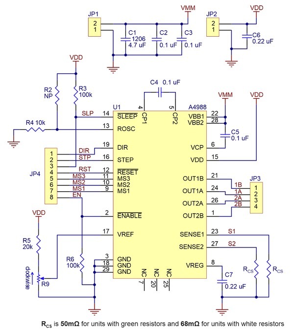
 This stepper motor driver module is a breakout/carrier board for Allegro’s A4988 DMOS Microstepping Driver with Translator and Overcurrent Protection and is Pololu / StepStick compatible. This stepper motor driver lets you control a bipolar stepper motor at 1 A continuous current per phase without a heatsink or cooling, and at up to 2 A maximum output current per coil if additional cooling is provided. An onboard potentiometer is used to adjust the current output.
This driver can control the stepper motor with just 2 pins from the controller, one for controlling the rotation direction and the other for controlling the steps. Stepper motors typically have a step size specification (e.g. 1.8° or 200 steps per revolution), which applies to full steps. A microstepping driver such as this one allows higher resolutions by allowing intermediate step locations, which are achieved by energizing the coils with intermediate current levels. For instance, driving a motor in quarter-step mode will give the 200-step-per-revolution motor 800 microsteps per revolution by using four different current levels. The resolution (step size) selector inputs (MS1, MS2, MS3) enable selection from the five-step resolutions according to the table below.
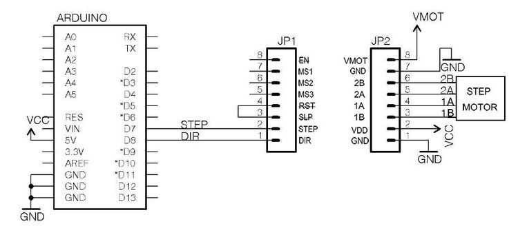
The translator is the key to the easy implementation of the A4988. Simply inputting one pulse on the STEP input drives the motor one microstep, while the MS1 through MS3 input pins control the microstep resolution. There are no phase sequence tables, high-frequency control lines, or complex interfaces to program. The A4988 interface is ideal for applications that do not have a complex microprocessor available, and pairs well with Arduino microcontrollers.
Specifications:
- Operating voltage: 8 V minimum to 35 V maximum
- Continuous current per phase: 1 A
- Maximum current per phase: 2 A (with cooling)
- Logic voltage: 3 V minimum to 5.5 V maximum
- Thermal shutdown circuitry
- Ground fault protection
- Load short-circuit protection
- Microstep resolutions: Full, 1/2, 1/4, 1/8 and 1/16
Pinout Description:
VDD and Ground: 3 V to 5.5 V support power.
1A and 1B: Connected to one coil of the motor.
2A and 2B: Connected to the other coil of the motor.
VMOT and Ground: 8 V to 35 V for powering the motor. We recommend using a decoupling capacitor of at least 47 µF for protecting the driver board from voltage spikes.
DIRECTION: Controls the rotation direction of the motor and should be connected to one of the digital pins of your microcontroller. Pulling it HIGH drives the motor clockwise and pulling it LOW drives the motor counterclockwise. If you just want the motor to rotate in a single direction, you can tie DIR directly to VCC or GND accordingly.
STEP: Controls the microsteps of the motor. Each HIGH pulse sent to this pin steps the motor by number of microsteps set by Microstep Selection Pins MS1 – MS3. The faster the pulses, the faster the motor will rotate.
SLEEP: A logic low puts the board in sleep mode for minimizing power consumption when the motor is not in use. It is an active low input, meaning pulling this pin low puts the driver in sleep mode, minimizing the power consumption.
RESET: Sets the translator to a predefined Home state, as defined in the A4988 Datasheet. These are the initial positions from where the motor starts and they are different depending on the microstep resolution. It is also an active low input. When pulled low, all STEP inputs are ignored until you pull it high. If you are not using the pin, you can connect it to the adjacent SLEEP pin to bring it high and enable the driver.
ENABLE: Turns on or off the FET outputs. The enable pin can be left disconnected, it is pulled low by default. When this pin is set high the driver is disabled.
MS1, MS2 and MS3: Select one of the five-step resolutions according to the table below. These pins have internal pull-down resistors so if they are disconnected, the board will operate in full-step mode.

| MS1 | MS2 | MS3 | Microstep Resolution |
| Low | Low | Low | Full step |
| High | Low | Low | Half step |
| Low | High | Low | Quarter step |
| High | High | Low | Eighth step |
| High | High | High | Sixteenth step |
Other References:
How To Control a Stepper Motor with A4988 Driver and Arduino tutorial and video on HowToMechatronics: http://envistia.info/a4988howto
Control Stepper Motor with A4988 Driver Module & Arduino by Last Minute Engineers: https://envistia.info/a4988lme.
Allegro A4899 IC datasheet: https://envistia.info/a4988ds
Copyright © 2017-2022 Envistia Mall
www.envistiamall.com
P/N EM-MOTOR-0002