
Search for your product name or keyword
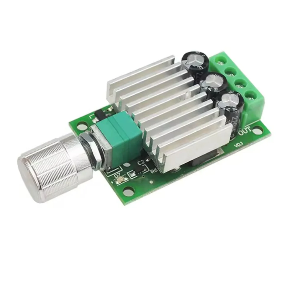
12-30VDC 7A PWM DC Motor Speed Controller Regulator with On-board Potentiometer and On/Off Switch
 This section provides a comprehensive guide to using your 12-30VDC 7A PWM DC Motor Speed Controller. This controller allows you to precisely control the speed of your DC motors using Pulse Width Modulation (PWM) technology. It is designed for a wide range of applications, from hobby projects to small manufacturing setups.
Introduction
This PWM DC Motor Speed Controller allows you to easily adjust the speed of a DC motor within a 12-30VDC range. The speed is controlled by adjusting the duty cycle of the PWM signal using the on-board potentiometer. The controller is equipped with several features to ensure reliable and safe operation, including over-current, over-temperature, and short-circuit protection.
Features
- High Current Capacity: Handles an average continuous current of 7A and a peak current of 10A, ideal for controlling high-power DC motors. Ensures efficient and reliable performance even under demanding conditions.
- Wide Voltage Range (12-30V DC): Compatible with a broad range of power supplies and DC motors, offering flexibility for diverse applications.
- Precise PWM Speed Control: Fine-tune your motor’s speed with the adjustable duty cycle (5%-100%) using the onboard potentiometer. Achieve smooth and accurate speed adjustments for optimal performance.
- Integrated On/Off Switch: Conveniently turn the controller on and off with the built-in switch integrated into the potentiometer (fully counter-clockwise click).
- Built-in Protection: Features overload, over-temperature, and short-circuit protection, safeguarding your motor and system from potential damage and extending motor lifespan.
- Durable and Reliable Design: Built with high-quality components and a robust circuit design for exceptional durability and long-lasting performance.
- Power Indicator LED: On-board LED illuminates when power is applied and the controller is turned on, providing a visual indication of operation.
- Easy to Use: Simple to install and operate, making it suitable for both beginners and experienced users.
Specifications
- Input supply voltage: 12-30 VDC
- Maximum continuous output current: 7A, 10A Peak
- Duty Cycle (Speed Range): Adjustable 5% to 100%
- On/Off switch: Built into potentiometer (fully counter-clockwise clicks off)
- Power Indicator: On-board LED illuminates when power is applied to the module and the module is turned on
- Dimensions: 50mm x 32mm x 19mm (1.97in x 1.26in x 0.75in) (LxWxH) excluding potentiometer shaft
Safety Precautions
- Voltage Limits: Ensure the input voltage is within the specified range of 12-30VDC. Exceeding this voltage can damage the controller.
- Current Limits: Do not exceed the maximum continuous output current of 7A or the peak current of 10A. Doing so may trigger the over-current protection or damage the controller.
- Polarity: Ensure correct polarity when connecting the power supply to the “Power +” and “Power -” terminals. Reverse polarity can damage the controller.
- Fuse Protection: Important: We strongly recommend adding an appropriately rated fuse inline with the positive supply to protect the circuit from potential short circuits. Choose a fuse rated slightly above the expected continuous current draw of your motor.
- Heat Dissipation: For continuous operation at high currents, consider adding a heatsink to the controller to prevent overheating.
- Grounding: Ensure proper grounding of the power supply.
- Operating Environment: Avoid operating the controller in excessively humid or dusty environments.
Operating Instructions
Step 1: Power Off
- Turn the potentiometer fully counter-clockwise until it clicks. This ensures the module is turned off before making any connections.
Step 2: Motor Connection
- Connect your DC motor (or DC load) to the “Motor +” and “Motor -” terminals as labeled on the back of the circuit board.
Step 3: Power Connection
- Connect a DC voltage of 12V-30V to the “Power +” and “Power -” terminals. Ensure correct polarity. The voltage applied to the motor will be the same as the supply voltage.
- Critical Note: The ground connections to the power supply and the motor must be separate connections. Do not tie the “Power -” and “Motor -” connections together; otherwise, the controller will not function correctly. See the connection diagram below.
Step 4: Fuse Installation (Highly Recommended)
- Install an appropriately rated fuse in-line with the positive (Power +) supply wire. This will protect the controller and your motor from short circuits.
Step 5: Power On and Speed Control
- Turn the unit on by rotating the potentiometer clockwise. The on-board power LED should illuminate, indicating that the controller is powered on.
- You can now control the motor’s speed by adjusting the potentiometer. Rotating the potentiometer clockwise increases the motor speed, while rotating it counter-clockwise decreases the speed.
Troubleshooting
- Motor not running:
- Verify that the power supply is connected and providing the correct voltage (12-30V DC).
- Ensure the controller is turned on (potentiometer rotated clockwise).
- Check the motor connections for correct polarity and secure connections.
- Verify that the “Power -” and “Motor -” connections are separate and not tied together.
- Check the fuse (if installed) and replace if necessary.
- If the LED is not lit, there is no power to the controller.
- Motor running erratically:
- Check for loose connections.
- Ensure the power supply voltage is stable.
- The motor may be drawing too much current. Try a smaller motor or a higher-rated controller.
- Controller overheating:
- Reduce the motor load or use a lower voltage.
- Consider adding a heat sink to the controller.
- The motor may be drawing too much current.
Where to Buy the 12-30VDC 7A PWM DC Motor Speed Controller
12-30VDC 7A PWM DC Motor Speed Controller on the Envistia Mall website:
https://envistiamall.com/products/12-30vdc-7a-pwm-dc-motor-speed-controller
Copyright © 2025 Envistia Mall
www.envistiamall.com
P/N EM-MOTOR-0009