
Search for your product name or keyword
SD Memory Card Storage Board Read / Write Module with SPI Interface
 This page provides information on how to use the SD Card SPI Read/Write Module with your Arduino, AVR, ARM, or PIC microcontroller projects. This module allows you to easily read and write data to SD cards using the SPI communication protocol.
Introduction
The SD Card SPI Read/Write Module is a convenient way to add data logging and storage capabilities to your microcontroller projects. It communicates with your microcontroller via the SPI interface, allowing you to read and write files to standard SD cards. The module includes a built-in logic level converter, making it compatible with both 5V and 3.3V microcontrollers.
Features
- SPI Interface: Uses the SPI protocol for communication, a common and well-supported interface for many microcontrollers.
- SD Card Compatibility: Supports standard SD cards (SD, SDHC).
- On-board Logic Level Conversion: Automatically adapts to either 5V or 3.3V logic levels, simplifying integration with different microcontrollers.
- Easy Integration: Designed for easy connection to Arduino, AVR, ARM, and PIC microcontrollers.
- Compact Design: Small form factor for easy integration into projects.
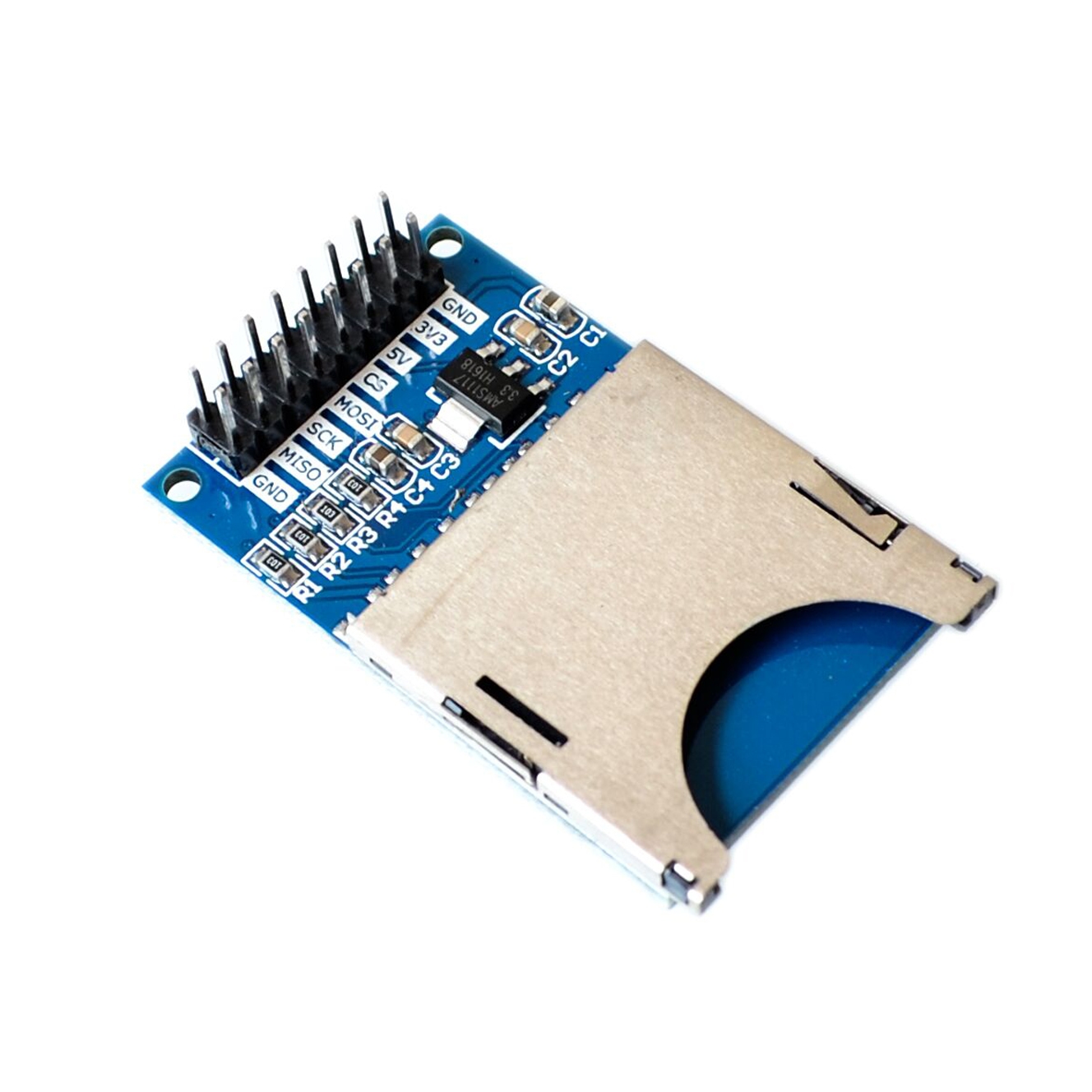
Pinout and Description
The module has the following pins:
| Pin Label | Description |
|---|---|
| GND | Ground |
| 3.3V | 3.3V Power Supply Input. Connect to 3.3V if using a 3.3V microcontroller, or leave unconnected if using 5V. |
| 5V | 5V Power Supply Input. Connect to 5V if using a 5V microcontroller. |
| CS | Chip Select (SPI Slave Select) |
| SCK | Serial Clock (SPI Clock) |
| MOSI | Master Out Slave In (SPI Data Output from Microcontroller) |
| MISO | Master In Slave Out (SPI Data Input to Microcontroller) |
| GND | Ground |
Important Note: You only need to connect either the 3.3V pin or the 5V pin, depending on the voltage of your microcontroller. Connecting both simultaneously may damage the module.
Connecting to a Microcontroller (Example: Arduino)
This section provides an example of how to connect the SD Card SPI Read/Write Module to an Arduino board. The connections will be similar for other microcontrollers, but you may need to consult your microcontroller’s documentation for specific pin assignments.
- Insert the SD Card: Carefully insert the SD card into the SD card slot on the module. Ensure it is properly seated.
- Connect the Power Supply: Connect either the 3.3V or 5V pins to the corresponding power supply pin on your microcontroller. Connect one of the GND pins to the GND pin on your microcontroller.
- Connect the SPI Pins: Connect the SPI pins as follows:
- Module CS -> Arduino Digital Pin (e.g., Pin 10 – can be changed in software)
- Module SCK -> Arduino SCK (Digital Pin 13)
- Module MOSI -> Arduino MOSI (Digital Pin 11)
- Module MISO -> Arduino MISO (Digital Pin 12)
Wiring Diagram (Example – Arduino):
| Module Pin | Arduino Pin |
|---|---|
| GND | GND |
| 5V | 5V |
| CS | 10 |
| SCK | 13 |
| MOSI | 11 |
| MISO | 12 |
| GND | GND |
Software, Libraries and Sample Code
To use the SD Card SPI Read/Write Module with your microcontroller, you will need to use a suitable library. For Arduino, the built-in SD library is commonly used.
- Install the SD Library (Arduino): The
SDlibrary is included with the Arduino IDE. No installation is required. - Example Code (Arduino):
#include <SPI.h>#include <SD.h>const int chipSelect = 10; // Chip Select pin connected to the modulevoid setup() {Serial.begin(9600);while (!Serial) {; // wait for serial port to connect. Needed for native USB port only}Serial.print("Initializing SD card...");if (!SD.begin(chipSelect)) {Serial.println("initialization failed!");while (1);}
Serial.println("initialization done.");// Create a fileFile myFile = SD.open("test.txt", FILE_WRITE);// If the file opened okay, write to it:if (myFile) {
Serial.print("Writing to test.txt...");myFile.println("testing 1, 2, 3.");// close the file:myFile.close();Serial.println("done."); }else {
// if the file didn't open, print an error:Serial.println("error opening test.txt");}// Re-open the file for readingmyFile = SD.open("test.txt");if (myFile) {Serial.println("test.txt content:");// read from the file until there's nothing else in it:while (myFile.available()) {Serial.write(myFile.read());}// close the file:myFile.close();}else {// if the file didn't open, print an error:Serial.println("error opening test.txt");}}void loop() {// nothing happens after setup} - This example code initializes the SD card, creates a file named “test.txt”, writes “testing 1, 2, 3.” to the file, closes the file, re-opens the file, reads the contents, and prints them to the serial monitor.
- Adapt for Other Microcontrollers: For AVR, ARM, or PIC microcontrollers, you will need to use appropriate SPI libraries and adapt the code accordingly. Consult your microcontroller’s documentation and search for suitable SD card libraries.
Troubleshooting
- SD Card Not Initializing:
- Check the wiring connections carefully. Ensure all pins are properly connected.
- Verify that the SD card is properly inserted into the slot.
- Ensure that you have selected the correct chip select pin in your code.
- Try a different SD card. Some SD cards may not be compatible.
- Double check that you are only connecting either the 3.3V or the 5V pin, not both.
- Data Corruption:
- Ensure that you are properly closing files after writing to them.
- Check the power supply voltage. An unstable power supply can cause data corruption.
- Code Not Compiling:
- Verify that you have included the necessary libraries in your code (
SPI.handSD.hfor Arduino). - Check for any syntax errors in your code.
- Verify that you have included the necessary libraries in your code (
Important Considerations
- SD Card Format: Ensure that the SD card is formatted with a FAT16 or FAT32 file system.
- Power Supply: Provide a stable and clean power supply to the module.
- Chip Select Pin: The chip select (CS) pin is crucial for SPI communication. Ensure it is properly configured and controlled in your code.
- Library Compatibility: Select a library that is compatible with your microcontroller and the SPI communication protocol.
By following these instructions, you should be able to successfully integrate the SD Card SPI Read/Write Module into your microcontroller projects and add data logging and storage capabilities. Remember to consult your microcontroller’s documentation and the library documentation for more detailed information.
Copyright © 2025 Envistia Mall
www.envistiamall.com
EM-OTHER-0016