
Search for your product name or keyword
L298N Dual H Bridge DC Stepper Motor PWM Drive Controller
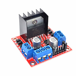 This L298N-based driver module is a high voltage, high current dual full-bridge driver designed to accept standard TTL logic levels and drive inductive loads such as relays, solenoids, DC and stepping motors from 5V to 35V. It can easily control the DC motor speed and direction, and can also control 2-phase stepper motors. It can be used for other projects such as driving the brightness of certain lighting projects such as high-powered LED arrays using Pulse Width Modulation (PWM) control.
Two enable inputs are provided to enable or disable the device independently of the input signals.
The motor direction is controlled by sending a HIGH or LOW signal to the drive for each motor (or channel). For example for motor A, a HIGH to IN1 and a LOW to IN2 will cause it to turn in one direction, and a LOW and HIGH will cause it to turn in the other direction.
The module includes an onboard 5V regulator. When enabled by the jumper, the 5V is provided as an output on the power connector and can be used as a 5V DC supply for your other circuit components.
When the onboard regulator is enabled (i.e. the jumper is installed), the input voltage to the +12V connector must be at least 6V, and the +5V connector can be used as an OUTPUT to power other 5V devices, such as your Arduino controller. When the regulator is disabled (i.e. the jumper is removed), a 5V INPUT must be provided on the +5V connector to control the logic level circuitry of this module, and a second DC voltage must be applied to the +12V connector to power the motor.
L298N Controller Parameters
- Driver chip: L298N dual H-bridge driver
- Drive Voltage: +5V to +35V (Input voltage must be at least 6V when internal 5V regulator is enabled)
- Drive peak current Io: 2A / Bridge
- Logic power supply range Vss : +4V to +5.5V DC (Not required when internal regulator is enabled. When enabled, the 5V is available as an output on the power connector
- Control signal input voltage range: 4.5-5.5V high 0V low
- Maximum power consumption: 20W
- Storage temperature: -25 ~ +130 C
- Dimensions (approx): 43mm x 43mm x 27mm LxWxH (1.7″ x 1.7″ x 1.1″)
- Weight: 26g
L298N Wiring and Operation

The module has two screw terminal blocks for motors A and B, and another screw terminal block for the VCC for motors, a 5V pin which can either be an input or output (see below), and Ground.
L298N Power Inputs/Outputs
When the onboard regulator is enabled (i.e. the jumper is installed), the input voltage to the +12V connector must be at least 6V, and the +5V connector can be used as an OUTPUT to power other 5V devices, such as your Arduino controller. When the regulator is disabled (i.e. the jumper is removed), a 5V INPUT must be provided on the +5V connector to control the logic level circuitry of this module, and a second DC voltage must be applied to the +12V connector to power the motor.
If the motor voltage is greater than 12V, the regulator jumper must be disconnected because voltages over 12V will damage the onboard 5V regulator. In this case, the +5V pin will be used as input, and a 5V power supply must be connected to it in order to power the logic level circuitry.
There is an internal voltage drop of about 2V, so, for example, with 12V Vcc, the voltage at motor terminals will be about 10V. To provide a full 12V to the motors, you will need to provide a Vcc voltage of about 14V.
L298N Logic Interconnections
The EnA and EnB (Enable A and Enable B) pins are used for enabling and controlling the speed of the motor. If a jumper is installed on these pins, the motors will be enabled and work at maximum speed. If the jumpers are removed, a PWM input can be connected to these pins to control the speed of the motors. If the EnA or EnB pin is connected to ground, the motor will be disabled.
IN1 and IN2 pins are used to control the rotation direction of motor A, and IN3 and IN4 for motor B. These pins control the switches of the H-Bridge inside the L298N. If IN1 is LOW and IN2 is HIGH the motor will move forward. If IN1 is HIGH and IN2 is LOW the motor will move backward. If both pins are same, either LOW or HIGH, the motor will stop. To provide an output voltage on the Motor terminal blocks, either IN1 or IN2 MUST be HIGH. If one of these pins is not pulled high, there will be no output to the motor. The same applies to IN3 and IN4 for motor B.
For examples of how to control the L298N module using an Arduino or other microcontroller, see the articles and associated code samples below.
Other L298N Information & References
How to Use the L298 Motor Driver Module on Instructables: http://www.instructables.com/id/How-to-use-the-L298-Motor-Driver-Module-Arduino-Tu/
How to use the L298N Motor Driver on Arduino.cc: https://create.arduino.cc/projecthub/ryanchan/how-to-use-the-l298n-motor-driver-b124c5
L298N Motor Driver – Arduino Interface, How It Works, Codes, Schematics on How To Mechatronics: https://howtomechatronics.com/tutorials/arduino/arduino-dc-motor-control-tutorial-l298n-pwm-h-bridge/
Interface L298N DC Motor Driver Module with Arduino on LastMinuteEngineers: https://lastminuteengineers.com/l298n-dc-stepper-driver-arduino-tutorial/
Youtube: HOW TO video:
Copyright © 2017-2022 Envistia Mall
www.envistiamall.com
P/N EM-MOTOR-0001