
Search for your product name or keyword
KY-023 Dual Axis XY Game Joystick Sensor Module Controller
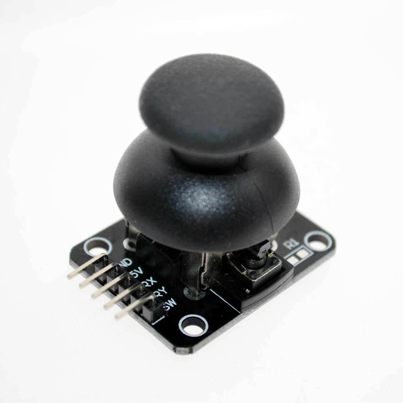 This support page details the usage of the KY-023 Dual Axis XY Game Joystick Sensor Module Controller, designed for use with Arduino, AVR, PIC, and other microcontrollers. This module allows for intuitive two-axis control and incorporates a push-button switch for added functionality.
Introduction
The KY-023 joystick module is an excellent input device for various projects, including robotics, remote control systems, and interactive games. It provides analog X and Y axis readings, reflecting the joystick’s position, and a digital signal from the integrated push-button switch. This makes it a versatile component for DIY electronics projects.
Features
- Dual-Axis XY Joystick: Provides analog readings for X and Y axis movement.
- Integrated Push-Button Switch: Offers a digital input for on/off control or mode switching.
- Self-Centering: The joystick auto-returns to the middle position.
- Compact Design: Small form factor for easy integration into projects.
- Simple Interface: Clearly labeled pins for easy connection to microcontrollers.
- Wide Compatibility: Compatible with Arduino, AVR, PIC, and other microcontrollers.
How the KY-023 Joystick Module Works
The joystick module uses two 10K-Ohm potentiometers which are placed at a 90-degree angle for reading the operator’s input. One potentiometer is used to obtain the analog output voltage for X-direction movement whereas the other one is for Y-direction movement. They are connected between +VCC and GND, so they simply perform as voltage divider networks. These are connected to a small joystick centered through springs. Whenever the joystick is in a resting position, the output will be approximately 2.5 volts (assuming a 5V VDC input). When the joystick is moved, the output changes from 0 Volts to 5 Volts based on its direction.
For the correct x-y orientation, i.e., for the x-axis to be horizontal and the y-axis to be vertical, the module should be oriented with the pins facing to the left.
These modules’ construction is very simple and low cost but useful in various applications like general experimenting & incorporating into , robotic control, camera and gaming applications.
Specifications
- Dimensions: 34mm (L) x 26mm (W) x 32mm (H)
- Axes: X and Y (Analog)
- Switch: Push-Button (Digital)
- Operating Voltage: 3.3V to 5V DC
- Interface: 5-pin header
- Potentiometer Type: 10K Ohm ±20%, linear taper
- Switch Activation: Pulls to ground when pressed.
Pinout and Connection
The KY-023 module has a 5-pin header with the following connections:
| Pin | Label | Description |
|---|---|---|
| 1 | +3.3Vcc to +5Vcc | Positive supply voltage. Connect to the 3.3V or 5V pin on your microcontroller. 5V is recommended |
| 2 | GND | Ground. Connect to the GND pin on your microcontroller. |
| 3 | VRx | Analog output for the X-axis. Connect to an analog input pin (e.g., A0, A1, A2) on your microcontroller. The voltage level on this pin will vary depending on the X-axis position of the joystick. |
| 4 | VRy | Analog output for the Y-axis. Connect to an analog input pin (e.g., A1, A2, A3) on your microcontroller. The voltage level on this pin will vary depending on the Y-axis position of the joystick. |
| 5 | SW | Digital output for the push-button switch. Connect to a digital input pin (e.g., D2, D3, D4) on your microcontroller. This pin is normally HIGH and is pulled LOW when the button is pressed. Note: This pin requires an internal or external pull-up resistor. |
Example Wiring Diagram (Arduino)
Connect the KY-023 module to your Arduino board as follows:
- KY-023 +5Vcc -> Arduino 5V
- KY-023 GND -> Arduino GND
- KY-023 VRx -> Arduino A0
- KY-023 VRy -> Arduino A1
- KY-023 SW -> Arduino D2
Important: Since the switch pin (SW) pulls to ground when pressed, you will need to enable the internal pull-up resistor on the Arduino pin D2 in your code.
Example Arduino Code
_____________________________________________________________________________________
const int joystickXPin = A0;    // X-axis analog input pin
const int joystickYPin = A1;    // Y-axis analog input pin
const int switchPin = 2;       // Switch digital input pin

int xValue = 0;                // Variable to store the X-axis value
int yValue = 0;                // Variable to store the Y-axis value
int switchState = 0;           // Variable to store the switch state

void setup() {
  Serial.begin(9600);          // Initialize serial communication

  pinMode(switchPin, INPUT_PULLUP); // Set the switch pin as an input with internal pull-up resistor
}

void loop() {
  // Read the analog values from the joystick
  xValue = analogRead(joystickXPin);
  yValue = analogRead(joystickYPin);

  // Read the digital value from the switch
  switchState = digitalRead(switchPin);

  // Print the values to the serial monitor
  Serial.print("X: ");
  Serial.print(xValue);
  Serial.print(", Y: ");
  Serial.print(yValue);
  Serial.print(", Switch: ");
  Serial.println(switchState);

  delay(100);                 // Delay for 100 milliseconds
}
_____________________________________________________________________________________
Explanation of the Code
const int joystickXPin = A0;: Defines the analog pin connected to the X-axis output.const int joystickYPin = A1;: Defines the analog pin connected to the Y-axis output.const int switchPin = 2;: Defines the digital pin connected to the switch output.pinMode(switchPin, INPUT_PULLUP);: Configures the switch pin as an input and enables the internal pull-up resistor. This ensures the pin is HIGH when the button is not pressed.xValue = analogRead(joystickXPin);: Reads the analog value from the X-axis pin (range: 0-1023).yValue = analogRead(joystickYPin);: Reads the analog value from the Y-axis pin (range: 0-1023).switchState = digitalRead(switchPin);: Reads the digital value from the switch pin (HIGH or LOW).Serial.print(...);: Prints the values to the serial monitor for debugging and observation.
Calibration and Usage Tips
- Centering: The joystick may not be perfectly centered at rest. You can compensate for this in your code by subtracting an offset value from the X and Y readings. Determine the offset by reading the values when the joystick is at rest.
- Dead Zones: Implement a “dead zone” in your code to ignore small movements around the center position, preventing unintended actions. This can be done by checking if the absolute value of the difference between the current reading and the center offset is greater than a certain threshold.
- Analog Range: The analog readings from the joystick will range from 0 to 1023. You may need to map these values to a different range depending on your application (e.g., -100 to 100 for motor control).
- Switch Debouncing: If you experience erratic behavior from the switch, implement a software debouncing routine to filter out spurious signals caused by mechanical switch bounce.
Troubleshooting
- No readings: Double-check the wiring connections and ensure the module is properly powered (5V).
- Erratic readings: Ensure the ground connections are secure. Try adding a small capacitor (e.g., 0.1uF) between the +5Vcc and GND pins on the KY-023 module to filter out noise.
- Switch not working: Verify the connection to the digital pin and ensure the pull-up resistor is enabled (either internally or externally). Check for shorts in the wiring.
- Values not centered: Follow the calibration steps described in section 7.
Applications
- Robotics Control: Control the movement of a robot arm or mobile robot.
- Remote Control Systems: Build a remote control for various devices.
- Game Controllers: Create custom game controllers for PC or other platforms.
- Menu Navigation: Use the joystick for navigating menus on a display.
- IoT Projects: Integrate the joystick into IoT devices for user input.
Safety Precautions
- Always disconnect the power supply before making any wiring changes.
- Ensure the operating voltage is within the specified range (5V DC).
- Avoid exposing the module to excessive moisture or extreme temperatures.
This user manual section provides a comprehensive guide to using the KY-023 Dual Axis XY Game Joystick Sensor Module Controller. By following these instructions and guidelines, you can successfully integrate this module into your electronics projects. Remember to consult datasheets for your specific microcontroller for detailed information on analog and digital input configurations.
Where to Buy the KY-023 Dual Axis XY Game Joystick Sensor Module Controller
KY-023 Dual Axis XY Game Joystick Sensor Module Controllers on the Envistia Mall website:
One Piece: https://envistiamall.com/products/dual-axis-xy-game-joystick-sensor-module-controller-for-arduino-avr-pic-diy
2-Piece Pack: https://envistiamall.com/products/2x-dual-axis-xy-game-joystick-sensor-module-controller-for-arduino-avr-pic-diy-ky-023
Copyright © 2025 Envistia Mall
EM-ECOMP-0005