
Search for your product name or keyword
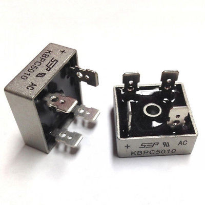
KBPC5010 1000V 50A Diode Bridge Rectifier
 This support page provides information for the safe and effective use of the KBPC5010 single-phase diode bridge rectifier. This rectifier is designed for various applications, including power supplies, motor controls, and battery chargers.
Introduction
The KBPC5010 is a single-phase bridge rectifier with a high surge current capability and an electrically isolated metal case for efficient heat dissipation. It is designed to convert AC voltage into DC voltage.
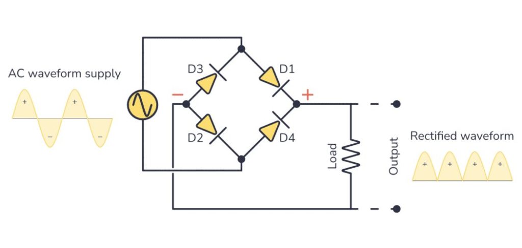
To rectify both half-cycles of a sine wave, the KBPC5010 bridge rectifier uses four diodes, connected together in a “bridge” configuration. The secondary winding of the transformer is connected on one side of the diode bridge network and the load on the other side. The image below shows the bridge rectifier circuit, and the resulting input and output voltage waveforms. To smooth the resulting pulsating DC current use a filter, most often a high-capacity capacitor, connected to the output.
Features
- High Voltage and Current: 1000V maximum repetitive peak reverse voltage and 50A maximum average forward rectified output current.
- UL Listed: UL listed under the Recognized Component Index, file number E142814.
- Flammability Rating: The plastic material used carries Underwriters Laboratory flammability recognition 94V-0.
- High Surge Current: Surge overload rating of 400A.
- Electrically Isolated Metal Case: Provides maximum heat dissipation and allows for easy mounting.
- Isolation Voltage: Case to terminal isolation voltage of 2500V.
- Universal Terminals: Universal 4-way terminals, snap-on, wrap-around, solder or P.C. Board mounting
Electrical Specifications
| Parameter | Symbol | Value | Unit |
|---|---|---|---|
| Maximum Repetitive Peak Reverse Voltage | VRRM | 1000 | V |
| Maximum RMS Bridge Input Voltage | VRMS | 700 | V |
| Maximum DC Blocking Voltage | VDC | 1000 | V |
| Maximum Average Forward Rectified Output Current at TA=40°C | IF(AV) | 50 | A |
| Peak Forward Surge Current (Single Sine-Wave Superimposed on Rated Load) | IFSM | 400 | A |
| Typical Thermal Resistance per Element | ReJA | 2.5 | °C/W |
| Operating Junction and Storage Temperature Range | Tj, TSTG | -55 to +150 | °C |
| Maximum Instantaneous Forward Voltage Drop per Leg at 25A | VF | 1.0 | V |
| Maximum DC Reverse Current at Rated TA=25°C | IR | 10 | uA |
| DC Blocking Voltage per Element at TA=125°C | IR | 500 | uA |
Pinout and Mechanical Specifications


Mounting
- Safety First: Ensure the power is off before beginning installation.
- Thermal Compound: Apply a thin, even layer of silicone thermal compound between the metal case of the rectifier and the mounting surface. This is crucial for efficient heat transfer.
- Mounting: Bolt the rectifier to the mounting surface using a screw through the center hole.
- Torque: Tighten the mounting screw to a maximum torque of 20 in-lb. Over-tightening can damage the device.
Wiring
The KBPC5010 has four terminals: two for AC input and two for DC output. The terminals are typically marked with symbols:
- ~ (AC): Connect the AC input voltage to these terminals.
- + (DC): Connect the positive DC output to this terminal.
- – (DC): Connect the negative DC output (ground) to this terminal.
Important: Verify the polarity of the DC output before connecting to your load. Incorrect polarity can damage the load.
Operating Conditions
Current: Do not exceed the maximum average forward rectified output current
Temperature: Ensure the operating temperature remains within the specified range of -55°C to +150°C.
KBPC5010 Manufacturer’s Datasheet (PDF)
KBPC5010 1000V 50A Bridge Rectifier Manufacturer’s Datasheet (PDF)
Where to Buy the KBPC5010 100V 50A Diode Bridge Rectifier
KBPC5010 1000V 50A Metal Case Single Phase Diode Bridge Rectifier on the Envistia Mall website:
https://envistiamall.com/products/kbpc5010-1000v-50a-metal-case-single-phase-diode-bridge-rectifier
Copyright © 2016–2025 Envistia Mall
EM-ECOMP-0031