
Search for your product name or keyword
Bi-Directional 4-channel 5V to 3.3V Logic Level Converter Module
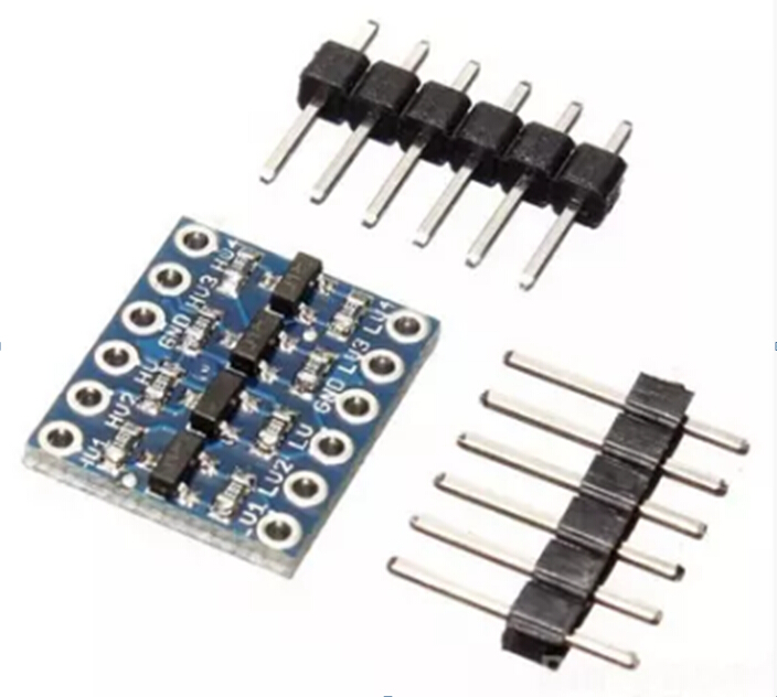 This document provides a comprehensive guide on how to use the 4-Channel Bi-Directional Logic Level Converter module to interface between 5V and 3.3V logic levels. This module is ideal for connecting 3.3V sensors and devices to 5V microcontrollers like Arduino, ensuring safe and reliable communication.
Introduction
The Bi-Directional Logic Level Converter allows you to seamlessly connect devices operating at different voltage levels. It simultaneously steps down 5V signals to 3.3V and steps up 3.3V signals to 5V on the same channel. This eliminates the need for separate converters and simplifies your project wiring. This module is particularly useful for I2C communication and Arduino projects.
Features
- Bi-Directional Voltage Conversion: Converts signals in both directions simultaneously.
- 4 Independent Channels: Supports four separate data channels for converting multiple signals.
- Wide Voltage Compatibility: Compatible with 1.8V, 2.8V, 3.3V, and 5V devices.
- I2C & Arduino Ready: Designed for I2C communication and Arduino projects.
- Safe & Reliable Protection: Protects 3.3V components from voltage damage.
- Easy Setup: Includes pre-soldered pin headers for easy connection.
Pinout and Connections
The Logic Level Converter has the following pins:
- HV: High Voltage side (e.g., 5V). Connect to the positive supply voltage of your 5V system.
- LV: Low Voltage side (e.g., 3.3V). Connect to the positive supply voltage of your 3.3V system.
- GND: Ground. Connect to the common ground of both your 5V and 3.3V systems.
- HV1, HV2, HV3, HV4: High Voltage side channels 1-4. Connect to the 5V signal lines.
- LV1, LV2, LV3, LV4: Low Voltage side channels 1-4. Connect to the 3.3V signal lines.
Important Note: Ensure that the ground connections of both the 5V and 3.3V systems are connected to the GND pin of the level converter. This is crucial for proper operation.
Wiring Instructions
Follow these steps to connect the Logic Level Converter:
- Power Connections:
- Connect the HV pin to the 5V supply.
- Connect the LV pin to the 3.3V supply.
- Connect the GND pin to the common ground of both the 5V and 3.3V systems.
- Signal Connections:
- Connect the 5V signal from your 5V device to one of the HV1, HV2, HV3, or HV4 pins.
- Connect the corresponding 3.3V signal to the corresponding LV1, LV2, LV3, or LV4 pin.
- Connect the Arduino’s 5V output pin to HV1.
- Connect the sensor’s 3.3V input pin to LV1.
Example Scenario: Connecting a 3.3V I2C Sensor to a 5V Arduino
This is a common use case for the Logic Level Converter. The I2C bus requires two signal lines: SDA (Serial Data) and SCL (Serial Clock).
- Power Connections: As described in section 5.
- I2C Signal Connections:
- Connect the Arduino’s SDA pin to HV1.
- Connect the sensor’s SDA pin to LV1.
- Connect the Arduino’s SCL pin to HV2.
- Connect the sensor’s SCL pin to LV2.
- Arduino Code: Use the standard Arduino Wire library to communicate with the I2C sensor. The Arduino will now be able to communicate with the 3.3V I2C sensor without risking damage.
Important Considerations
- Digital Signals Only: This level converter is designed for digital signals only. It cannot be used to convert analog voltages.
- Voltage Limits: Ensure that the voltage applied to the HV pin does not exceed 6V, and the voltage applied to the LV pin is at least 1.8V.
- Ground Connection: A common ground between the 5V and 3.3V systems is essential for proper operation.
- Unused Channels: You don’t need to use all four channels. Leave unused channels disconnected.
- Direction: The converter automatically handles the direction of the signal. No manual direction control is required.
Troubleshooting
- No Communication:
- Double-check all wiring connections.
- Ensure that the HV and LV pins are connected to the correct voltage supplies.
- Verify that the ground connection is secure.
- Check the voltage levels on the HV and LV sides with a multimeter.
- Unstable Signals:
- Ensure that the voltage supplies are stable and within the specified range.
- Check for any noise or interference on the signal lines.
- Try adding small decoupling capacitors (e.g., 0.1uF) close to the power pins of the module.
Where to Buy the 4-Channel Bi-Directional 5V to 3.3V Logic Level Converter Module
Bi-Directional 4-Channel 5V to 3.3V Logic Level Converter Module at Envistia Mall
Conclusion
The Bi-Directional Logic Level Converter is a valuable tool for any electronics enthusiast working with different voltage levels. By following these instructions, you can easily and safely interface 3.3V devices with 5V systems, expanding the possibilities of your projects.
Copyright © 2016-2025 Envistia Mall
www.envistiamall.com
EM-OTHER-0008