
Search for your product name or keyword
HC-05 Bluetooth Wireless RS-232 Master_Slave Transceiver Module
 This HC-05 Bluetooth RF transceiver module is a Bluetooth V2.0/2.1 device that has a serial UART layer on top of the Bluetooth. The UART layer simplifies operation by separating the Bluetooth functions from the user.
The HC05 has two modes of operation: AT command mode and transmission mode. When in AT command mode all data received over the serial UART connection is treated as a command, and when in transmission mode, all data received over the serial UART connection is treated as data. When in communication mode, if there is an active connection the data is broadcast to the connected device.
The HC-05 can operate as either a slave or master device. Slave devices cannot initiate connections, they can only accept them. Master devices can initiate and sometimes accept them. If you want to use the module with a mobile device such as an Android phone, the phone will be the master device and so the HC-05 will need to be the slave. If you want to link two HC-05s, one will need to be a master and the other one a slave.
Specifications
- Integrated Bluetooth Serial Pass-through Module Master-Slave 6 Pin JY-MCU anti-reverse
- Bluetooth 2.0 EDR using the CSR BC417 chip
- Can be a slave or a master device
- Has 2 modes: AT mode and communication mode
- Default baud rate for AT mode is 38400
- Default baud rate for communication is 9600
- Default pairing password is 1234, the default name is HC-05
- AT commands can be either lowercase or uppercase. AT commands require “\r\n” line endings
- Input Vcc voltage: 3.6V to 6V, on-board chip regulates working voltage to 3.3V
- Fully compatible with Arduino
- Coverage up to 10 meters (30 feet) with built-in antenna
- Working current: When unpaired, current of about 30mA; when pairing is successful, current reduces to about 10mA
- PCB Dimensions: 37mm x 15.5mm
Interconnection Wiring
To use AT commands we need to communicate with the HC-05 over the serial UART channel. There are 2 typical ways of doing this; with a USB to serial UART adapter, or with an Arduino and a serial in – serial out sketch.
If using a serial UART adapter simply connect and open the Arduino serial monitor. Be aware that the main window will only display the replies from the HC-05.
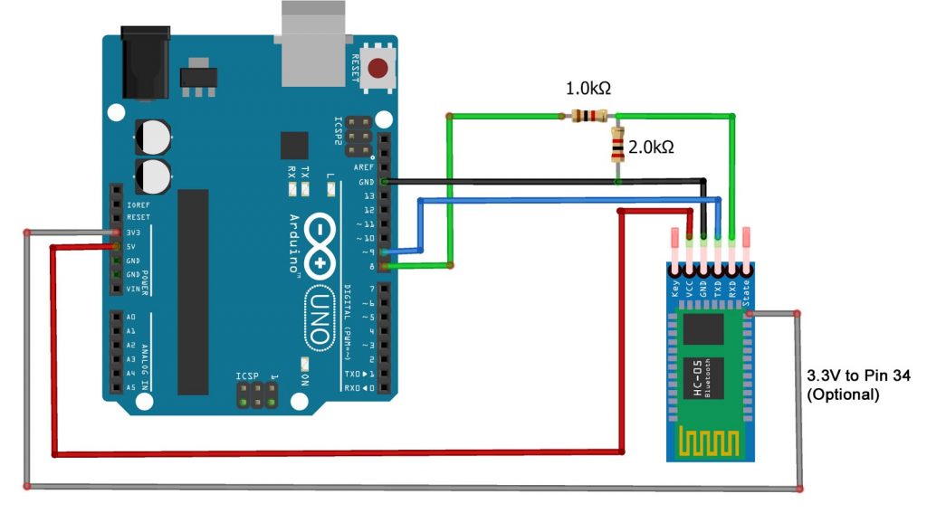
For the example below we use an Arduino Uno R3 and a serial sketch. This setup echos the commands to the serial monitor so we can clearly see what is happening.
The RX pin on the HC-05 is 3.3V, and the TX of the Arduino is 5V, therefore when connecting to an Arduino, a voltage divider should be used to reduce the 5V TX line to 3.3V, as shown in the diagram below. The line between the HC-05 TX pin and the Arduino RX pin can be connected directly because the 3.3V signal from the HC-05 is enough to be accepted as a high logic at the Arduino Board, therefore you do not need a voltage divider on the HC-05 TX line.
The support power can be 3.6 to 6 volts, because the breakout board contains a 3.3V voltage regulator to power the HC-05’s circuitry.
See the “AT Command Mode” section below for more details on the optional 3.3V/Pin 34 connection.
HC-05 LED
When first powered on, the LED flashes quickly about 10 times a second.
After pairing the LED flash rate changes to a single quick flash every couple of seconds. When connected, the LED blinks quickly twice every couple of seconds. In AT command mode the LED blinks 1 second on, 1 second off.
AT Command Mode
To put the HC-05 into AT command mode pin 34/PIO11 has to be HIGH on power up.
On the HC-05 breakout board (bottom right corner above the “EN” pin) there is a small push button switch. When closed, it connects pin 34/PIO11 to +3.3v, therefore, to put the HC-05 into AT command mode, we can use the button switch.
If you are doing a lot of work in AT command mode you can solder a wire directly to pin 34 and connect it to +3.3v, as shown in the wiring diagram above.
To enter AT mode:
- Power off the module
- Press and hold the small button switch
- Re-apply power while holding the button switch closed
- When you see the LED come on, release the button switch
When in AT command mode the LED flash rate will change to 1 second on, 1 second off.
Some commands do not work when in AT command mode and pin 34 is not HIGH. Therefore, some commands need you to close the switch before sending.
If you are doing a lot of work in AT command mode you can solder a wire directly to pin 34 and connect it to +3.3v, as shown in the wiring diagram above.
To return to communication mode, set pin 34 not HIGH (LOW or floating), and cycle the power to the module.
Arduino Sketch
This Arduino sketch takes anything entered into the serial monitor, echos it back to the serial monitor’s main window, and then sends it to the Bluetooth module. Anything received from the Bluetooth module is displayed in the serial monitor.
To highlight the user-entered text, a “>” character is displayed at the start of the line.
Note that we are using 2 serial connections. One using the serial monitor on the host computer and one to talk to the Bluetooth module. These are separate and different and have separate baud rates which do not need to be the same. This can be a little confusing to people new to the Arduino.
The sketch INO file (in TXT format) can be downloaded here: http://envistia.info/hc05-serial-test-sketch-txt
Assuming we are in AT command mode you can send and receive commands to the HC-05:
In the Arduino IDE, got to Tools>>Serial Monitor to open up the serial monitor window.
The HC-05 requires AT commands to include line endings (\r\n) so after opening the serial monitor make sure “Both NL & CR” is selected:

Start by entering the command “AT”. If everything is connected correctly and you have successfully entered AT mode you should get an “OK” reply.
For a list of HC-05 AT commands, download the HC-05 datasheet here: http://envistia.info/hc-05-datasheet
More information
Thank you to Martyn Currey for his excellent articles on using the HC-05. For more information on using and programming the HC-05 see:
Arduino with HC-05 Bluetooth module – AT MODE
HC-05 (ZG-B23090W) Bluetooth 2.0 EDR modules
Arduino With HC-05 Bluetooth Module in Slave Mode
Information on the Aruino Uno R3 microcontroller: http://envistia.info/arduino-uno-r3-with-cable
Copyright © 2018-2024 Envistia Mall
www.envistiamall.com
P/N EM-COMMS-0005