
Search for your product name or keyword
DS3231 AT24C32 Real Time Clock Timer Module
 This document provides a comprehensive guide to using the DS3231 Real Time Clock (RTC) module with Arduino. This module is ideal for projects requiring accurate timekeeping, even when the main power is unavailable.
Introduction
The DS3231 module is a low-cost, high-precision I2C real-time clock (RTC) featuring an integrated temperature-compensated crystal oscillator (TCXO) and crystal for enhanced accuracy. It’s designed for ease of use with microcontrollers like Arduino. Key features include:
- Accurate Timekeeping: Maintains seconds, minutes, hours, day, date, month, and year.
- Battery Backup: Onboard battery backup (CR2032 – not included) ensures continuous timekeeping during power interruptions.
- Leap Year Compensation: Automatically adjusts for months with fewer than 31 days and includes leap year correction up to the year 2100.
- Programmable Alarms: Two independent time-of-day alarms.
- Square-Wave Output: Programmable square-wave output for timing or synchronization purposes.
- I2C Communication: Simple serial interface for easy communication with microcontrollers.
- Integrated EEPROM: Includes an AT24C32 EEPROM chip for storing additional data.
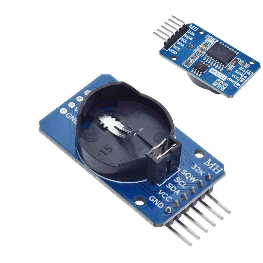
Module Overview
- DS3231M RTC Chip: The core of the module, responsible for timekeeping.
- AT24C32 EEPROM: 32K EEPROM chip for non-volatile data storage. The I2C address of the EEPROM can be modified using the A0/A1/A2 address selection jumpers.
- CR2032 Battery Holder: Holds the CR2032 battery (not included) for backup power.
- I2C Interface: SDA (Serial Data) and SCL (Serial Clock) pins for communication.
- SQW Pin: Square-wave output pin.
- VCC & GND: Power supply pins.
- A0, A1, A2 Jumpers: Used to modify the I2C address of the AT24C32 EEPROM.
Specifications
- Dimensions: 38mm x 22mm
- Weight: Approx 8g
- Working Voltage: 3.3V – 5.5V
- Clock Chip: High-precision DS3231M
- Memory Chip: AT24C32 (32K storage capacity)
- Clock Accuracy: 0-40°C, accuracy 2ppm, annual error about 1 minute
- Programmable Square-Wave Output: Yes
- Time-of-Day Alarms: Two
- Time Range: Seconds, minutes, hours, day, date, month, and year (up to 2100 with leap year compensation)
- I2C Bus Interface: Maximum transmission speed of 400KHz (at 5V)
- Default EEPROM Address: 0x57 (can be modified via A0/A1/A2 jumpers)
- Battery: CR2032 (not included)
Pinout
- GND: Ground
- VCC: Power Supply (3.3V – 5.5V)
- SDA: I2C Serial Data
- SCL: I2C Serial Clock
- SQW: Square-Wave Output
Getting Started with Arduino
Required Components
- DS3231 RTC Module
- Arduino Board (e.g., Arduino Uno, Nano, Mega)
- Jumper Wires
- CR2032 Battery (optional, for battery backup)
Hardware Connection
Connect the DS3231 module to your Arduino board as follows:
| DS3231 Module | Arduino |
|---|---|
| GND | GND |
| VCC | 5V (or 3.3V) |
| SDA | A4 (Arduino Uno/Nano) or SDA pin (Arduino Mega) |
| SCL | A5 (Arduino Uno/Nano) or SCL pin (Arduino Mega) |
| SQW | Digital Pin (Optional – for square wave output) |
Software Installation (RTClib Library)
The RTClib library simplifies communication with the DS3231 module. To install it:
- Open the Arduino IDE.
- Go to Sketch > Include Library > Manage Libraries…
- In the Library Manager, search for “RTClib”.
- Find the “RTClib by Adafruit” library.
- Click Install.
Example Code
#include <RTClib.h>
#include <Wire.h>

RTC_DS3231 rtc;

char daysOfTheWeek[7][12] = {"Sunday", "Monday", "Tuesday", "Wednesday", "Thursday", "Friday", "Saturday"};

void setup () {
  Serial.begin(9600);
  delay(3000); // Wait for console opening

  if (! rtc.begin()) {
    Serial.println("Couldn't find RTC");
    Serial.flush();
    abort();
  }

  if (rtc.lostPower()) {
    Serial.println("RTC lost power, lets set the time!");
    // When time needs to be set on a new device, or after a power loss, the
    // following line may be uncommented to set the date and time to the compiler date and time.
    rtc.adjust(DateTime(F(__DATE__), F(__TIME__)));
    // This line sets the RTC with an explicit date and time, for example to set
    // January 21, 2014 at 3am you would call:
    // rtc.adjust(DateTime(2014, 1, 21, 3, 0, 0));
  }
}

void loop () {
    DateTime now = rtc.now();

    Serial.print(now.year(), DEC);
    Serial.print('/');
    Serial.print(now.month(), DEC);
    Serial.print('/');
    Serial.print(now.day(), DEC);
    Serial.print(" (");
    Serial.print(daysOfTheWeek[now.dayOfTheWeek()]);
    Serial.print(") ");
    Serial.print(now.hour(), DEC);
    Serial.print(':');
    Serial.print(now.minute(), DEC);
    Serial.print(':');
    Serial.print(now.second(), DEC);
    Serial.println();

    Serial.print(" since midnight 1/1/1970 = ");
    Serial.print(now.unixtime());
    Serial.print("s = ");
    Serial.print(now.unixtime() / 86400L);
    Serial.println(" days");

    // Calculate a date which is 7 days into the future
    DateTime future = now + TimeSpan(7,12,30,6);

    Serial.print("Future date (7days, 12hours, 30minutes, 6seconds from now): ");
    Serial.print(future.year(), DEC);
    Serial.print('/');
    Serial.print(future.month(), DEC);
    Serial.print('/');
    Serial.print(future.day(), DEC);
    Serial.print(' ');
    Serial.print(future.hour(), DEC);
    Serial.print(':');
    Serial.print(future.minute(), DEC);
    Serial.print(':');
    Serial.print(future.second(), DEC);
    Serial.println();

    Serial.println();
    delay(3000);
}
Code Explanation
#include <RTClib.h>and#include <Wire.h>: Includes the necessary libraries.RTC_DS3231 rtc;: Creates an RTC object.rtc.begin();: Initializes the RTC module.rtc.lostPower();: Checks if the RTC lost power and needs to be set. If the RTC lost power, the example code sets the time to the time the code was compiled.rtc.adjust(DateTime(F(__DATE__), F(__TIME__)));: Sets the RTC to the current date and time from the compiler. This line should be commented out after the initial time setting to prevent resetting the RTC time on every upload.DateTime now = rtc.now();: Gets the current date and time from the RTC.now.year(), now.month(), now.day(), now.hour(), now.minute(), now.second(): Accesses individual time components.daysOfTheWeek[now.dayOfTheWeek()]: Gets the day of the week as a string.
Setting the Time
This example code sketch includes a section to set the time:
  if (rtc.lostPower()) {
    Serial.println("RTC lost power, lets set the time!");
    // When time needs to be set on a new device, or after a power loss, the
    // following line may be uncommented to set the date and time to the compiler date and time.
    rtc.adjust(DateTime(F(__DATE__), F(__TIME__)));
    // This line sets the RTC with an explicit date and time, for example to set
    // January 21, 2014 at 3am you would call:
    // rtc.adjust(DateTime(2014, 1, 21, 3, 0, 0));
  }
rtc.adjust(DateTime(F(__DATE__), F(__TIME__)));: This line sets the RTC to the compilation time of the sketch. Important: This line should be commented out after you’ve initially set the time. Otherwise, every time you upload the sketch, the RTC will be reset to the compilation time.rtc.adjust(DateTime(2014, 1, 21, 3, 0, 0));: This line shows an example of how to set a specific date and time. Replace the values with your desired date and time. Again, comment this line out after the initial time setting.
Running the Code
- Upload the code to your Arduino board.
- Open the Serial Monitor in the Arduino IDE (Tools > Serial Monitor).
- You should see the current date and time printed in the Serial Monitor.
I2C Address Modification
The default I2C address of the AT24C32 is 0x57. This can be modified by shorting the A0, A1, and A2 jumpers on the module. Each jumper corresponds to a bit in the I2C address. Leaving a jumper open sets the corresponding bit to 0, and shorting the jumper sets the bit to 1.
The I2C address is calculated as: 0x50 + (A2 << 2) + (A1 << 1) + A0
For example:
- All jumpers open (default): Address = 0x50 + 0 + 0 + 0 = 0x50 + 0x07 = 0x57
- A0 shorted, A1 and A2 open: Address = 0x50 + 0 + 0 + 1 = 0x51
- A0 and A1 shorted, A2 open: Address = 0x50 + 0 + 2 + 1 = 0x53
- All jumpers shorted: Address = 0x50 + 4 + 2 + 1 = 0x57
Important: If you modify the I2C address, you will need to update your Arduino code to reflect the new address.
Using the AT24C32 EEPROM
The DS3231 module also includes an AT24C32 EEPROM chip, which provides 32K of non-volatile storage. This can be used to store configuration data, sensor readings, or any other data that needs to be retained even when the power is off.
Using the EEPROM Library
You can use the EEPROM.h library that is included with the Arduino IDE to access the AT24C32 EEPROM. However, this library is designed for the Arduino’s built-in EEPROM. For larger EEPROMs like the AT24C32, it’s recommended to use a dedicated EEPROM library like MemoryFree. You may need to install this library using the Library Manager in the Arduino IDE.
Example code sketch using the MemoryFree library:
#include <Wire.h>
#include <MemoryFree.h>

#define EEPROM_ADDR 0x57 // Default EEPROM address (can be changed via A0/A1/A2 jumpers)

void setup() {
  Serial.begin(9600);
  Wire.begin(); // Initialize I2C

  // Write a value to EEPROM
  int address = 0;
  byte data = 42;
  EEPROM.writeByte(EEPROM_ADDR, address, data);
  Serial.print("Wrote ");
  Serial.print(data);
  Serial.print(" to address ");
  Serial.println(address);

  // Read the value from EEPROM
  byte readData = EEPROM.readByte(EEPROM_ADDR, address);
  Serial.print("Read ");
  Serial.print(readData);
  Serial.print(" from address ");
  Serial.println(address);

}

void loop() {
  // Nothing to do here
}
Using the Square-Wave Output (SQW)
The SQW pin can be configured to output a square wave signal. This can be useful for triggering other devices or for timing purposes. The frequency of the square wave can be programmed through the DS3231 registers. Refer to the DS3231 datasheet for details on configuring the SQW output.
Troubleshooting
- “Couldn’t find RTC” error:
- Check the wiring between the DS3231 module and the Arduino.
- Ensure the I2C pull-up resistors are present (usually included on the module).
- Verify that the correct I2C address is being used.
- Incorrect time:
- Make sure the time is being set correctly in the code.
- Ensure the battery is properly installed (if using battery backup).
- EEPROM not working:
- Verify the I2C address of the EEPROM.
- Check the wiring to the EEPROM.
- Make sure the EEPROM library is correctly installed and configured.
Further Information
- DS3231 Datasheet: Refer to the DS3231 datasheet for detailed information on the RTC chip’s registers and functionality (search the internet for “DS3231 Datasheet PDF).
- AT24C32 Datasheet: Refer to the AT24C32 datasheet for detailed information on the EEPROM chip’s registers and functionality (search the internet for “AT24C32 Datasheet PDF).
- RTClib Library Documentation: Consult the RTClib library documentation for more information on the available functions and options: https://github.com/adafruit/RTClib.
- Video: DS3231 Real Time Clock + Temperature Sensing using Arduino by Andrei Aldea on Youtube: https://www.youtube.com/watch?v=aSy2HB4pHJg
Where to Buy the DS3231 AT24C32 Real Time Clock Timer Module
DS3231 AT24C32 Real Time Clock Timer Module on the Envistia Mall Website:
Disclaimer
This user manual is provided for informational purposes only. The manufacturer is not responsible for any damages or losses resulting from the use of this product. Always exercise caution when working with electronic components.
Copyright © 2025 Envistia Mall
www.envistiamall.com
P/N EM-OTHER-0014