
Search for your product name or keyword
Arduino-Compatible Pro Micro ATMEGA32U4 5V 16MHZ Microcontroller
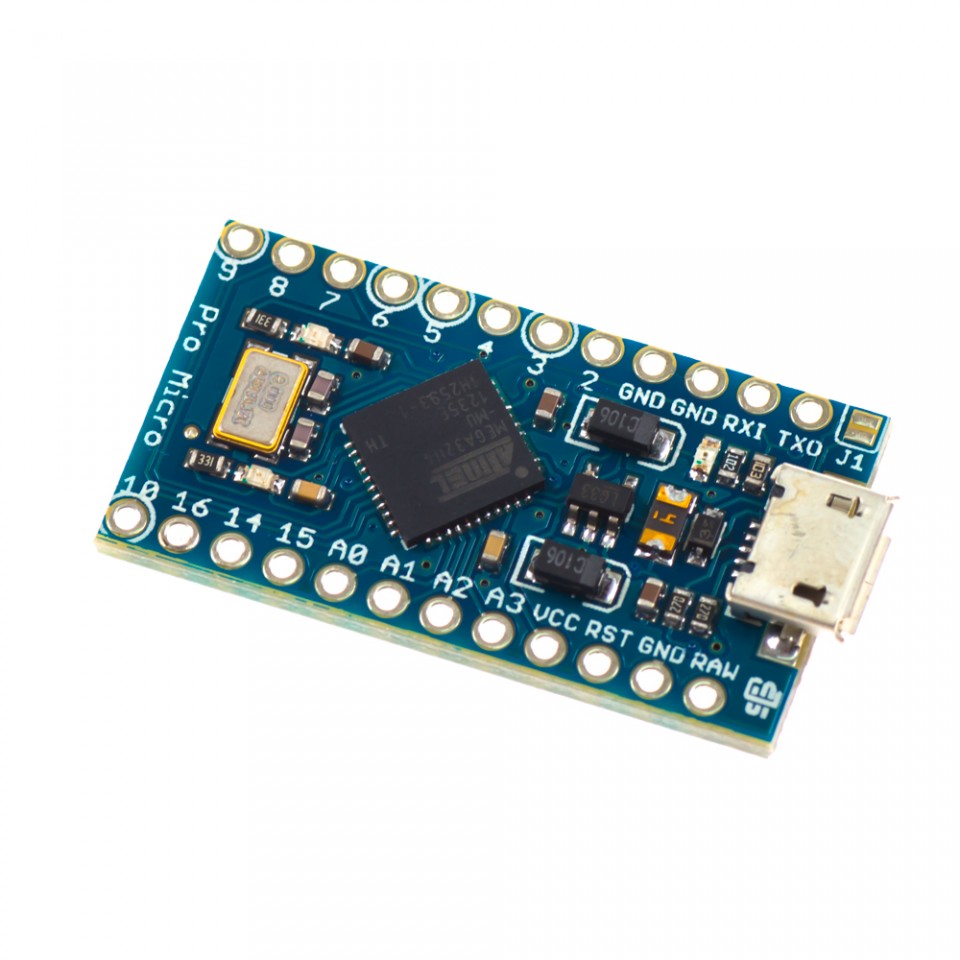 The Pro Micro is a small, powerful, and Arduino-compatible microcontroller board based on the ATmega32U4. It offers a compact solution for projects requiring a small footprint and integrated USB connectivity. This manual provides essential information for setting up and using your Pro Micro board.
Product Overview
The Pro Micro is similar to the Pro Mini but utilizes the ATmega32U4 microcontroller. The key advantage of the ATmega32U4 is its built-in USB transceiver, which eliminates the need for a separate USB-to-serial converter. This significantly reduces the board’s size and simplifies USB connectivity.
Features
- ATMega32U4 Microcontroller: Operates at 5V/16MHz.
- Arduino IDE Compatibility: Fully supported by Arduino IDE version 1.0.1 and later.
- Integrated Micro USB Connector: Simplifies programming and communication.
- Analog Inputs: 4 x 10-bit ADC pins for analog sensor readings.
- Digital I/O Pins: 12 x Digital I/O pins for controlling digital devices.
- PWM Outputs: 5 x Digital I/O pins are PWM (Pulse Width Modulation) capable for controlling motor speed, LED brightness, etc.
- Hardware Serial Communication: Dedicated Rx and Tx pins for reliable serial communication.
- Compact Size: Ideal for space-constrained projects.
- Voltage Regulation: On-board voltage regulator accepts input voltages up to 12VDC.
Pinout and Functionality
Understanding the pinout is crucial for connecting your Pro Micro to external components. Refer to the following table and diagram for detailed information.
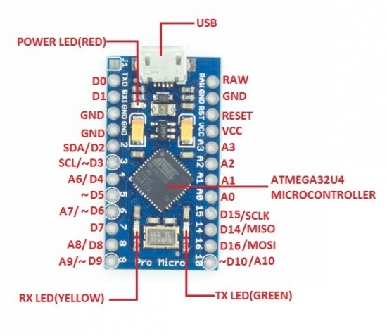
| Pin Name | Function | Description |
|---|---|---|
| VCC | Positive Supply Voltage (5V) | Connect to a regulated 5V power supply. |
| GND | Ground | Ground connection for the board. |
| RAW | Unregulated Voltage Input | Connect to an unregulated power supply (up to 12VDC). The on-board voltage regulator will step down the voltage to 5V. Do not connect to VCC if using RAW. |
| RST | Reset | Pulling this pin LOW will reset the microcontroller. |
| D0 – D13 | Digital I/O Pins | General-purpose digital input/output pins. Some pins also have special functions (see below). |
| A0 – A3 | Analog Input Pins | Analog input pins connected to the 10-bit ADC. |
| SDA | Serial Data (I2C) | Data line for I2C communication. |
| SCL | Serial Clock (I2C) | Clock line for I2C communication. |
| TX0 | Transmit (Serial) | Transmit pin for hardware serial communication. |
| RX1 | Receive (Serial) | Receive pin for hardware serial communication. |
| PWM Pins | D3, D5, D6, D9, D10 | These digital pins are capable of PWM output. |
Important Notes:
- Powering the Board: You can power the Pro Micro through the Micro USB connector (5V) or via the VCC (5V regulated) or RAW (unregulated up to 12V) pins. Never connect both VCC and RAW simultaneously.
- Soldering Header Pins: The included header pins need to be soldered to the board before you can easily connect it to other components.
Getting Started with the Arduino IDE
The Pro Micro is programmed using the Arduino IDE (Integrated Development Environment).
Installing the Arduino IDE
- Download the Arduino IDE from the official Arduino website: http://arduino.cc/en/Main/Software
- Follow the installation instructions for your operating system.
Configuring the Arduino IDE for the Pro Micro
- Connect the Pro Micro to your computer using a Micro USB cable.
- Open the Arduino IDE.
- Go to Tools > Board > Arduino Leonardo. (The Pro Micro uses the Leonardo bootloader)
- Go to Tools > Port and select the COM port that corresponds to your Pro Micro. If you’re unsure which port it is, disconnect and reconnect the Pro Micro and observe which new COM port appears in the list.
Uploading Your First Sketch
- Open the “Blink” example sketch: File > Examples > 01.Basics > Blink.
- Click the “Upload” button (the right-arrow icon).
- The Arduino IDE will compile the sketch and upload it to the Pro Micro.
- After the upload is complete, the LED connected to pin 13 on the Pro Micro should start blinking.
If you encounter issues uploading the sketch
- Double-check that you have selected the correct board (“Arduino Leonardo”) and COM port.
- Try pressing the reset button on the Pro Micro right before uploading. This can sometimes help to initiate the bootloader.
Example Projects
The Pro Micro is versatile and can be used in a wide range of projects. Here are a few example ideas:
- USB Keyboard/Mouse: The built-in USB functionality makes the Pro Micro ideal for creating custom keyboards, mice, and other input devices.
- Data Logger: Use the analog inputs to read sensor data and store it on an SD card (using an SD card module).
- Robotics Controller: Control motors, servos, and sensors in a small robot.
- IoT Device: Connect to the internet using a Wi-Fi or Ethernet module and control devices remotely.
Troubleshooting
- Board Not Recognized: If your computer doesn’t recognize the Pro Micro, try installing the Arduino drivers manually. Instructions for driver installation can be found below and on the Arduino website.
- Upload Errors: Double-check your board and port selections in the Arduino IDE. Try pressing the reset button before uploading.
- Code Not Working as Expected: Carefully review your code for errors. Use the Arduino IDE’s serial monitor to debug your code.
Installing Windows Drivers and Pro Micro Support for the Arduino IDE Board Manager
Before using this board, you may need to install the Windows Drivers, and the Pro Micro support to the Arduino IDE Board Manager. To do so:
- Follow the instructions here to install the drivers (scroll down to the “Installing” section: http://envistia.info/promicrohookupguide
- Follow the instructions here to install Pro Micro board support in the Arduino IDE (scroll down to “Installation Instructions”): http://envistia.info/github-arduino-promicro-board-def
- The Board type is “Arduino/Genuino Micro”
Resources and Further Information
- Getting Started with Arduino: http://www.arduino.cc/en/Guide/HomePage
- Arduino Software (IDE) download link: http://arduino.cc/en/Main/Software
Where to Buy the Pro Micro ATMEGA32U4 5V 16MHZ Microcontroller
Pro Micro ATMEGA32U4 5V 16MHZ Microcontroller on the Envistia Mall website:
https://envistiamall.com/products/pro-micro-atmega32u4-5v-16mhz-leonardo-arduino-compatible
This installation and operation guide provides a starting point for using your Arduino-compatible Pro Micro. We encourage you to explore the Arduino ecosystem and experiment with different projects. Good luck, and happy making!
Copyright © 2017-2025 Envistia Mall
EM-MICRP-0011