
Search for your product name or keyword
5V 4 Channel Relay Module 250V/10A Relays
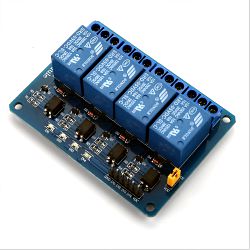 This 4-channel 5V control Single-Pole Double-Throw (SPDT) AC power relay board contains four 5V relays and the associated switching and isolating components, which makes interfacing with a microcontroller or sensor easy with minimum components and connections. Each channel can switch up to 10 amperes at 250 VAC and 30 VDC, and 15 amperes at 125VAC. Inputs are isolated with an optocoupler to protect any delicate control circuitry.
The inputs for this module are active low, meaning that the relay is activated when the signal on the input header is low (pulled to ground). This is because the indicator LED and the input of the optocoupler are connected in series to the VCC pin on one end, so the other end must be connected to the ground to enable the current flow.
When you have power connected to the relay’s NO (Normally Open) connector and you set the corresponding IN pin to LOW (0V, or Ground), power will flow in from the COMM connector and out of the NO connector powering your device.
Specifications:
- Polarity: Active Low – you must ground the control input to switch the relay ON
- Relay Max Switching Voltage: 250 Volts AC, 30VDC
- Relay Max Switching: Current: 10 Amps AC and DC
- Relay Control Voltage: 5.0V directly via microcontroller (Arduino, AVR, PIC, ARM, BoardX, Raspberry Pi, MSP430, etc)
- Relay Control Current: 50-60 mA per channel
- Each channel’s red LED (IN1 – IN4) illuminates when the control pin is pulled low (relay is activated)
- Size: 76mm x 56mm x 17mm (3.0 x 2.2 x 0.67 inches) L x W x H
- Weight: 60g
Four-Channel Relay Module Pinout
| Pin Number | Pin Name | Description |
| 1 | GND | Ground reference for the module |
| 2 | IN1 | Input to activate relay 1 |
| 3 | IN2 | Input to activate relay 2 |
| 4 | IN3 | Input to activate relay 3 |
| 5 | IN4 | Input to activate relay 4 |
| 6 | VCC | Power supply for the relay module |
| 7 | VCC | Power supply selection jumper |
| 8 | JD-VCC | Alternate power pin for the relay module |
The VCC – JD-VCC jumpers 7 & 8 let you connect the VCC power separately from the main input connector. Pin 7 on the VCC side is connected to the VCC pin 6 of the main connector. Pin 8 (JD-VCC) then connects the 5V to the rest of the module. If you connect the 5V input using the main connector pin 6, just leave the jumper in place. If you want to separate it, remove the jumper and connect your 5V input to the JD-VCC pin 8.
Additional Resources & Tutorials:
A tutorial for using relays with an Arduino microcontroller can be seen at
https://components101.com/switches/5v-four-channel-relay-module-pinout-features-applications-working-datasheet.
YouTube Video: How To Interface 5V 4 Channel Relay Module with Arduino
Copyright © 2018-2026 Envistia Mall
www.envistiamall.com
EM-ECOMP-0047