
Search for your product name or keyword
5MM T1-3/4 4 Pin Common Anode / Common Cathode Clear / Diffused RGB LED
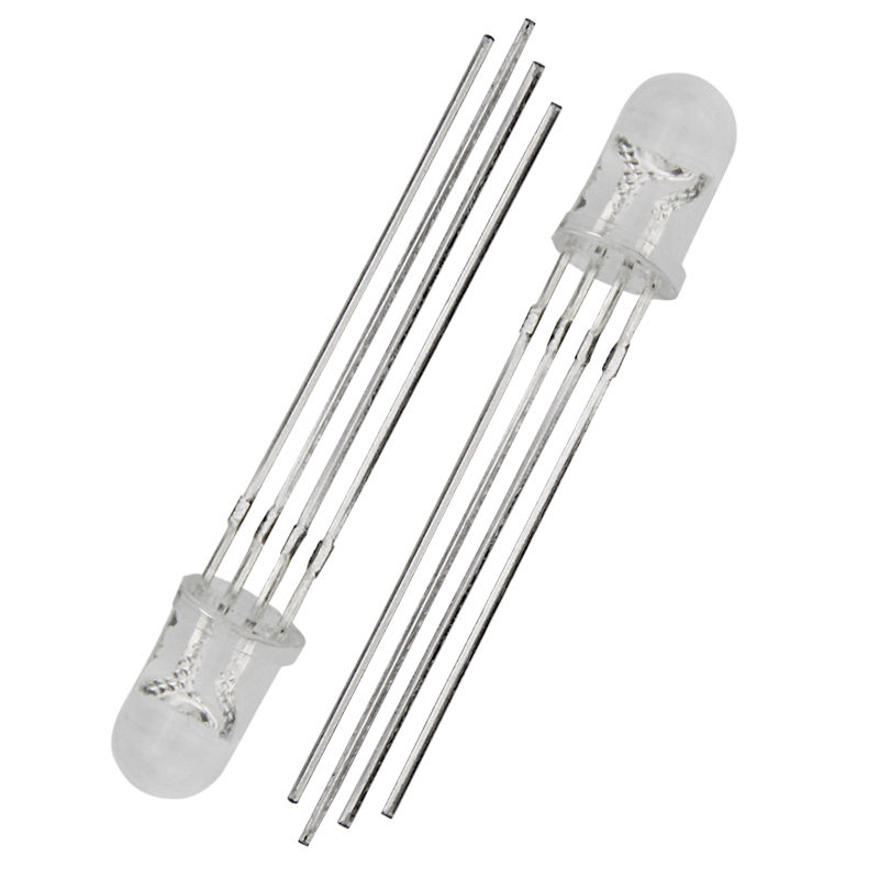 RGB LEDs are actually three LEDs, red, green, and blue, inside one package. Instead of 2 wires coming out, there are 4 wires coming out: The longest one is + Voltage (in Common Anode diodes, Ground in Common Cathode Diodes), and the 3 others correspond to red, green, and blue.
By varying the brightness of each LED, a single RGB LED can display the full spectrum of color. A specific color can be set through the choice of resistors in series with each color wire. By using the PWM outputs of an Arduino or other microcontroller, the brightness of each of the three LEDs can be controlled independently. A PWM value of 0.0 would be off and a 1.0 full on for each color LED. This allows a program to vary both the color and brightness level of the LED, providing dynamic control of the LED’s output color and brightness.
| Parameter | Clear | Diffused |
| Forward Voltage Vf (V) | ||
| Red | 2.25 | 2.25 |
| Green | 3.5 | 3.5 |
| Blue | 3.5 | 3.5 |
| Reverse Current | 100µA Max. | 100µA Max. |
| Dominant Wavelength | ||
| Red | 630-640 | 630-640 |
| Green | 515-525 | 515-525 |
| Blue | 465-475 | 465-475 |
| Luminous Intensity (mcd) | ||
| Red | 1000-1200 | 1000-1200 |
| Green | 3000-5000 | 3000-5000 |
| Blue | 2000-3000 | 2000-3000 |
| Viewing Angle | 60 degrees | 120 degrees |
| Tested at IF=20mA |
Operation
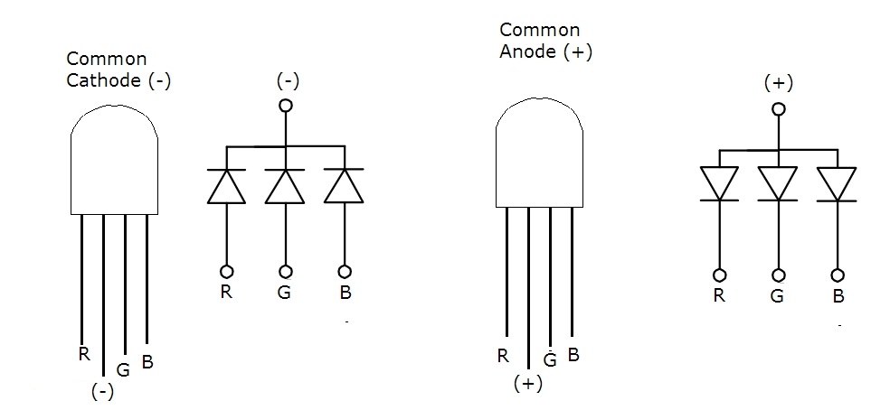
Common Anode: +V is connected to the anode pin “2”, Ground is connected to the remaining three pins corresponding to each color.
Common Cathode: Ground is connected to the cathode pin “2”, +V is connected to the remaining three pins corresponding to each color.
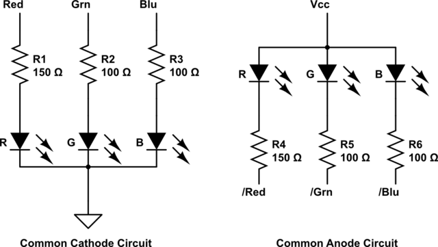
A voltage dropping resistor is needed to drop the output voltage of a digital logic signal to the operating voltage of the LED and to limit the current. See the example below. These resistor values are examples only. The values required for your application may vary. The value of the required dropping resistor can be calculated so that it drops down the voltage by the required amount from the digital logic output level (5 or 3.3V). Resistor values are typically around 100-330 ohms. The three LEDs inside a single RGB LED have different operating voltages. The voltage drop tends to rise as the frequency of the light wave increases.
The equations used to compute the correct resistance for an LED can be found in this Wikipedia series resistance formula: http://envistia.info/wikiledcalc
or use this web page calculator: http://envistia.info/digikeyledcalc
Additional Resources
“A Simple Guide to RGB LEDs” on buildelectroniccircuits.
“Interfacing RGB Led with Arduino” on the Arduino Project Hub.
Where to Buy the 5MM 4 Pin RGB LEDs
5MM 4pin Common Anode Clear RGB LED at Envistia Mall
5MM 4pin Common Anode Diffused RGB LED at Envistia Mall
Copyright © 2017-2026 Envistia Mall
www.envistiamall.com
EM-LEDLI-0003-CL / EM-LEDLI-0003-DI