
Search for your product name or keyword
10A/20A/30A PWM Solar Charge Controllers
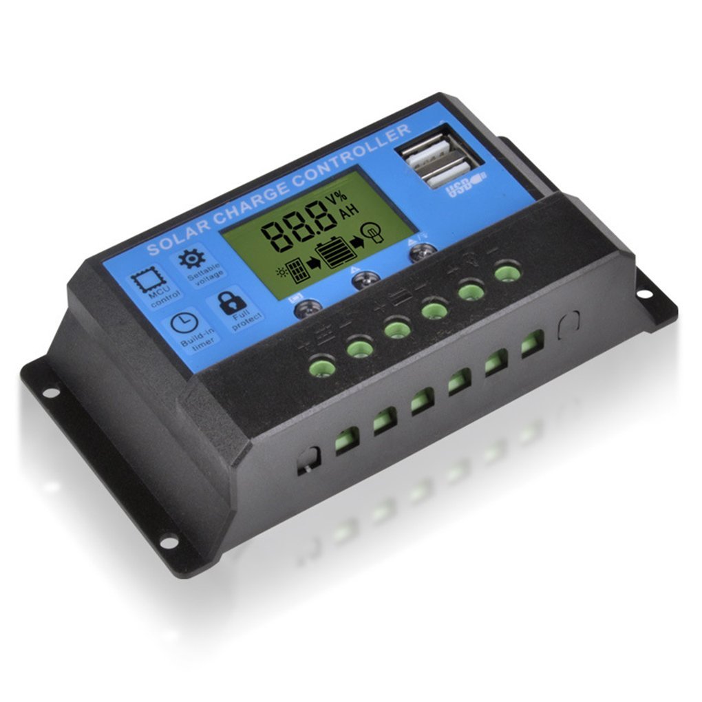 These 10A, 20A and 30A PWM Solar Battery Charge Controllers automatically manage and regulate the voltage and current to the battery from the solar panel(s). They incorporate short-circuit, open-circuit, reverse polarity, and overload protection in order to ensure that the batteries are not overcharged and that power isn’t discharged from the batteries to the solar panels during shaded or dark conditions and drain the batteries. They come with USB ports to charge your phone and other electronic devices directly from the controller.
Maximum Ratings
The maximum input charging current from the solar panel is 10A, 20A or 30A depending upon the model chosen. The maximum panel output current should be about 25% less than the controller’s maximum input current rating.
For example, with a single 6A 100W panel, use the 10A model. Two 6A panels (12A total) should use the 20A model. If in doubt, use the higher current model, i.e. if the maximum panel output current is 9A, use the 20A model rather than the 10A model.
Maximum Input Voltage
12V batteries should be used with solar panels capable of generating 18V-25V
With 12V batteries, the maximum panel voltage must not exceed 25V
24V batteries should be used with solar panels capable of generating 36V-50V
With 24V batteries, the maximum panel voltage must not exceed 50V
Maximum Input Power
10A Model 12V: 120W (MAX), 24V: 240W (MAX)
20A Model 12V: 240W (MAX), 24V: 480W (MAX)
30A Model 12V: 360W (MAX), 24V: 720W (MAX)
Maximum Discharge Current / Power
The maximum discharge current to the load is 10A. Therefore with 12V batteries, the maximum power is 120 Watts. With 24V batteries, it is 240 Watts.
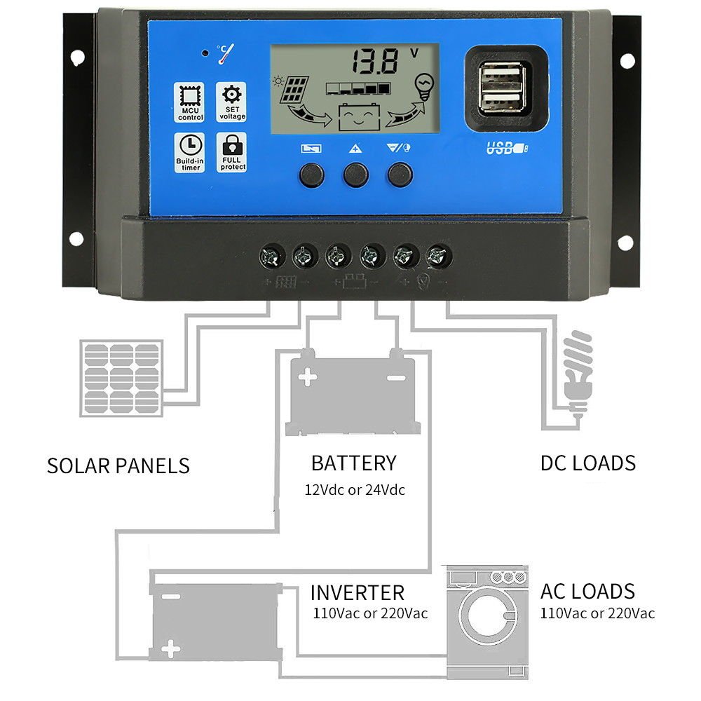
Connection to the Battery, Solar Panel and Load
- Make sure your battery has enough voltage (typically 10V or more) to power on the controller and to recognize the battery type.
- The battery cables should be as short as possible to minimize losses.
- The controller is only suitable for lead-acid batteries: Open, AGM and Gel. It is not suitable for nickel-metal hydride, lithium-ion, or other battery types.
This charge controller uses the battery voltage to operate its onboard circuitry, including its self-protection and control circuitry. If the controller is not powered on, connecting a live solar panel to it may damage the controller.
WARNING: The connection and disconnection sequence is critical. Do not connect your solar panel to the controller until the battery is first connected and the LCD is turned on, and disconnect the solar panel before disconnecting the battery. Failure to follow this sequence can damage the charge controller!
Connection and Disconnection Sequence
- Connect the battery to the charge controller first. The controller’s LCD should turn on. Do not proceed if the LCD display does not turn on! The controller needs about 10V to operate. If the LCD does not turn on it is usually because the battery cannot provide at least 10V. Charge it using an external battery charger before proceeding.
- Connect the photovoltaic module to the charge controller.
- Connect your load (the device(s) you are going to power) to the charge controller.
Reverse these steps when disconnecting or uninstalling the controller.
Display
There are three icons along the bottom of the display for the panels, the battery, and the load. If the battery is charging, there will be an arrow between the panel and the battery. See the attached image. If the LCD arrow is on, it is charging. If it is off, it is not charging. If it is flashing, it is maintaining the float voltage.
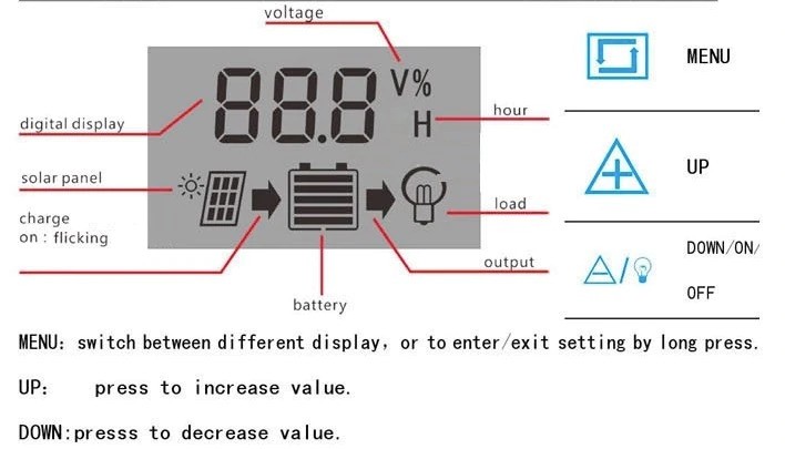
Referring to the buttons below the display, the left button is the “Menu” button (also used to Set and Select), the middle is the “Up” button and the right button is the “Down” button.
Tapping the Menu button will scroll through the different parameters.
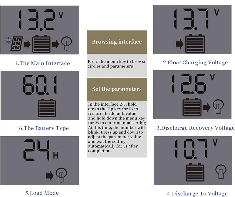
The sequence of the display is:
- Battery Voltage (V)
- Float Voltage (V)
Adjustable, sets the battery voltage at which the panel is disconnected from the battery to prevent overcharging of the battery)
Typical Values: 13.5 Volts to 14 Volts. Never set the Float Voltage higher than 14.1 V for gel batteries. Exceeding this can cause permanent gel damage. Gel batteries are especially sensitive to overcharge (gassing), so err on the lower side of charging voltages when in doubt. - Discharge Voltage Reconnection Level (V)
Adjustable, sets the battery voltage at which the solar panel is reconnected to the battery to initiate charging
Typical Values: 12.4 Volts to 12.6 Volts. - Low Voltage Disconnection (Discharge Stop) (V)
Adjustable, the voltage at which the battery is disconnected from the load to protect the battery from over-discharge
Typical Values: 10.5 Volts to 12 Volts. NOTE: The maximum value that these controllers allow is 11.5 Volts. To optimize battery life, we recommend setting the Discharge Stop to 11.5 Volts. - Load Working Mode (H)
Adjustable: 24H = the load output is on 24 hours per day
1-15H = The load output is on from sunset for the number of hours programmed
0H = The load output is on from dusk to dawn - Battery Type
Adjustable:
b1 = Sealed & AGM (Absorbent Glass Mat) Lead Acid
b2 = Gel
b3 = Flooded
NOTE: The Typical Values listed above are guidelines. Manufacturer datasheets should be consulted for specific model recommendations as there can be minor variations in these values.
Operating and Programming The Controller
Tap the Menu (left) button to cycle through the interface and parameters.
To change a parameter
- Cycle through the display until the parameter you want to change is displayed
- Long press the menu button for about 3 seconds to enter the programming mode. The value will begin flashing.
- Use the Up and Down buttons the change the value
- Tap the Menu button to save the setting. Tape it again to continue cycling through the parameters
Troubleshooting
| Indicator | Probable Cause | Solution |
| Charge icon not on when sunny | Solar panel opened, disconnected or reversed | Reconnect the solar panel |
| Load icon off | Mode setting wrong Battery Low | Set the Mode again Recharge the battery |
| Load icon slow flashing | Over load Short circuit | Reduce load wattage Remove short circuit, automatic recover after ~1 minute |
| Power off | Battery too low or reversed | Check battery and recharge if needed, check the connection |
Manufacturer’s Datasheet (PDF)
10A/20A/30A PWM Solar Charge Controller Manufacturer’s Datasheet (PDF)
Where to Buy 10A/20A/30A PWM Solar Charge Controllers
PWM Solar Charge Controllers at Envistia Mall
Other Solar Charge Controller Resources & Videos
How to Setup a Solar Charge Controller (menu, battery type & wiring) from Scott’s Solar Projects on Youtube
Copyright © 2018-2025 Envistia Mall
www.envistiamall.com
P/N EM-SOLAR-0001 / EM-SOLAR-0005